This tool helps calculate the impedance of an edge coupled microstrip.
Outputs
Overview
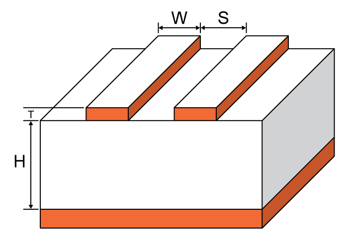
This calculator is designed to calculate the characteristic impedance of an edge coupled microstrip. Such a microstrip is constructed with two traces referenced to the same reference plane with a dielectric material between them. One of the features of this type of microstrip is the coupling between lines.
To use this tool, enter the values for trace thickness, substrate height, trace width, trace spacing and subtrate dielectric in the calculator above and press the "calculate" button. The outputs impedances can be odd, even, common and differential. See below for the definition of these impedances. The default units for all given values, except the subtrate dielectric, is in millimetres. It is possible to select other units.
Equations
$$Z_{0_{odd}}=Z_{0_{surf}}\cdot \left [ \frac{\sqrt{\frac{er_{eff}}{er_{effo}}}}{1-\left ( \frac{zo_{surf}}{\eta_{o}}\cdot q_{10}\sqrt{er_{eff}} \right )} \right ]$$
$$Z_{0_{even}}=Z_{0_{surf}}\cdot \frac{\sqrt{\frac{er_{eff}}{er_{eff,e}}}}{1-\frac{zo_{surf}}{\eta_{o}}\cdot q_{4}\cdot \sqrt{er_{eff}}}$$
Where:
$$Z_{0_{surf}}=\frac{\eta_{o}}{2\pi \sqrt{2}\sqrt{er_{eff}+1}}\cdot \ln \left ( 1+\left ( 4\cdot \frac{h}{w_{eff}} \right )\cdot \left (\left ( 4\cdot \frac{h}{w_{eff}} \right )\cdot\left ( \frac{14\cdot er_{eff}+8}{11\cdot er_{eff}} \right )+ temp \right )\right )$$
$$er_{eff1}=\frac{er+1}{2}+\left ( \frac{er-1}{2} \right )\cdot \left ( \sqrt{\frac{w}{w+12h}}+.04\left ( 1-\frac{w}{h} \right )^{2} \right )$$
$$er_{eff2}=\frac{er+1}{2}+\left ( \frac{er-1}{2} \right )\cdot \left ( \sqrt{\frac{w}{w+12h}} \right )$$
$$a_{0}=.7287\left ( er_{eff}-\frac{er+1}{2} \right )\cdot \left ( \sqrt{1-e^{-.179u}} \right )$$
$$b_{0}=\frac{.747\cdot er}{.15+er}$$
$$c_{0}=b_{0}-\left ( b_{0}-.207 \right )\cdot e^{-.414u}$$
$$d_{0}=.593+.694e^{-.562u}$$
$$g=\frac{s}{h}$$
$$w_{eff}=w+\frac{t}{\pi }\cdot \ln \left ( \frac{4e}{\sqrt{\left ( \frac{t}{h} \right )^{2}+\left ( \frac{t}{w\pi +1.1t\pi } \right )^{2}}} \right )\cdot \frac{er_{eff}+1}{2\cdot er_{eff}}$$
$$er_{effo}=\left ( \left ( .5\cdot \left ( er+1 \right )+a_{0}-er_{eff} \right )\cdot e^{-c_{0}\cdot g^{d_{0}}} \right )+er_{eff}$$
$$temp=\sqrt{16\left ( \frac{h}{w_{eff}} \right )^{2}\cdot \left ( \frac{14\cdot er_{eff}+8}{11\cdot er_{eff}} \right )^{2}+\left ( \frac{er_{eff}+1}{2er_{eff}} \right )\cdot \pi ^{2}}$$
$$q_{1}=.8695\cdot u^{.194}$$
$$q_{2}=1+.7519\cdot g+1.89g^{2.31}$$
$$q_{3}=.1975+\left ( 16.6+\left ( \frac{8.4}{g} \right )^{6} \right )^{-.387}+\frac{1}{241} \cdot \ln \left ( \frac{g^{10}}{1+\left ( \frac{g}{3.4} \right )^{10}} \right )$$
$$q_{4}=\frac{2\cdot q_{1}}{q_{2}\left ( e^{-g}\cdot u^{q_{3}}+\left ( 2-e^{-g} \right )\cdot u^{-q_{3}} \right )}$$
$$q_{5}=1.794+1.14\cdot \ln \left ( 1+\left ( \frac{.638}{g+.517\cdot g^{2.43}} \right ) \right )$$
$$q_{6}=.2305+\frac{1}{281.3}\cdot \ln \left ( \frac{g^{10}}{1+\left ( \frac{g}{5.8} \right )^{10}} \right )+\frac{1}{5.1}\cdot \ln \left ( 1+.598\cdot g^{1.154} \right )$$
$$q_{7}=\frac{10+190\cdot g^{2}}{1+82.3\cdot g^{3}}$$
$$q_{8}=e^{\left(-6.5 -.95\cdot\ln (g) -\left (\frac{g}{.15}\right )^{5}\right)}$$
$$q_{9}=\ln \left ( q_{7} \right )\cdot \left ( q_{8}+\frac{1}{16.5} \right )$$
$$q_{10}=\left ( \frac{1}{q_{2}} \right )\cdot \left ( q_{2}\cdot q_{4}-q_{5}\cdot e^{\left ( \ln\left ( u \right )\cdot q_{6}\cdot u^{-q_{9}} \right )} \right )$$
$$v=\frac{u\cdot \left ( 20+g^{2} \right )}{10+g^{2}}+ge^{-g}$$
$$ae(v)=1+\frac{\ln \left ( \frac{v^{4}+\left ( \frac{v}{52} \right )^{2}}{v^{4}+.432} \right )}{49}+\frac{\ln \left ( 1+\left ( \frac{v}{18.1} \right )^{3} \right )}{18.7}$$
$$b_{e}(e_{r})=.564\left ( \frac{er-.9}{er+3} \right )^{.053}$$
$$er_{eff,e}=\frac{er+1}{2}+\frac{er-1}{2}\cdot \left ( 1+\frac{10}{v} \right )^{-a}\cdot e^{v}\cdot b_{e}(e_{r})$$
Notes:
Odd Impedance ($$Z_{0_{odd}}$$): The impedance between one differential trace and the ground plane with the differential signals are driven with opposite polarity.
$$Z_{0_{odd}}=\frac{Z_{0_{diff}}}{2}$$
Even Impedance ($$Z_{0_{even}}$$): The impedance between one differential trace and the ground plane with the differential signals are driven with the same signal.
$$Z_{0_{even}} = 2Z_{0_{common}}$$
Differential Impedance ($$Z_{0_{diff}}$$): The impedance between the two lines with opposite polarity signals.
$$Z_{0_{diff}} = 2Z_{0_{odd}}$$
Common Impedance ($$Z_{0_{common}}$$):The impedance between the two lines with the same signal.
$$Z_{0_{common}}=\frac{Z_{0_{even}}}{2}$$
Applications
Microwave antennas and couplers as well as some filters can be created using the edge-coupled microstrip. These transmission lines are popular because they can be manufactured cheaper than the traditional waveguide and are also more portable. The disadvantage of edge-coupled microstrips is their limited power-handling capabilities. Other issues with such transmission lines are high power loss, cross-talk, and unintentional radiation. Edge-coupled microstrips also find themselves in high-speed digital PCB design where differential signals are handled.


0 Comments Login