

This is probably the most important part of the ALLBOT manual, here we explain how a regular ARDUINO SKETCH for any ALLBOT might look. This chapter will be divided up into several sections:
- Installing the ARDUINO IDE
- Connecting your ARDUINO
- Testing your ARDUINO
- Explaining the ALLBOT LIBRARY
- Letting your ALLBOT chirp
- Creating a movement routine
- Adding VR001 IR remote functionality
INSTALLING THE ARDUINO IDE
First off you have to install the ARDUINO IDE, you can find the latest version to download here: https://www.arduino.cc/en/Main/Software. Choose the right file for your operating system and install the software once it has downloaded.
CONNECTING YOUR ARDUINO
When the install of the ARDUINO IDE has been completed you need to connect your ARDUINO UNO or ARDUINO MEGA with your computer. You can do this using a USB A->B cable. Once connected your computer will install the necessary drivers. Once that has been completed you can start the ARDUINO IDE. You will need to select the correct BOARD and PORT so the software knows where it has to send you sketches to. You can do this by following these steps:
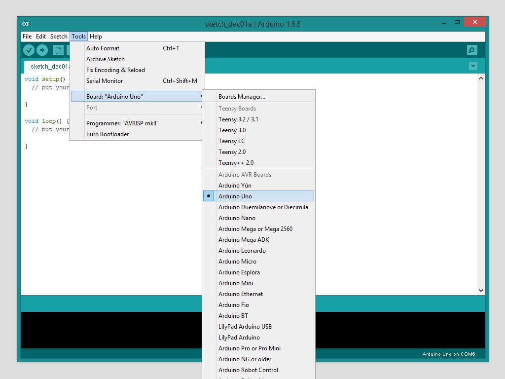
SETTING THE CORRECT BOARD:
TOOLS -> BOARD -> ARDUINO UNO or ARDUINO MEGA
SETTING THE CORRECT PORT:

TESTING YOUR ARDUINO
To test if you ARDUINO UNO or ARDUINO MEGA is working correctly we are going to use the “Blink” example. This is a piece of example code that makes the led on your board blink. To open this code follow these steps:
FILE -> EXAMPLES -> 01. BASICS -> BLINK

The following code should open:
|
1 2 3 4 5 6 7 8 9 10 11 12 13 14 15 16 17 18 19 20 21 22 23 24 25 26 27 |
/* Blink Turns on an LED on for one second, then off for one second, repeatedly. This example code is in the public domain. */ // Pin 13 has an LED connected on most Arduino boards. // Pin 11 has the LED on Teensy 2.0 // Pin 6 has the LED on Teensy 2.0 // Pin 13 has the LED on Teensy 3.0 // give it a name: int led = 13; // the setup routine runs once when you press reset: void setup() { // initialize the digital pin as an output. pinMode(led, OUTPUT); } // the loop routine runs over and over again forever: void loop() { digitalWrite(led, HIGH); // turn the LED on (HIGH is the voltage level) delay(1000); // wait for a second digitalWrite(led, LOW); // turn the LED off by making the voltage LOW delay(1000); // wait for a second } |
Now you can press the UPLOAD button (the one next to the VERIFY button in the top left corner) and the ARDUINO IDE will compile and upload that code to your board.
Make sure the the PROGRAM/IR RECEIVE switch on the VRSSM SHIELD is set to program if you want to start programming your ARDUINO. When it is set to IR RECEIVE it will not be possible to program your ARDUINO.
If you tried programming you ARDUINO with this switch set to IR RECEIVE you will need to disconnect your ARDUINO, close the ARDUINO IDE, reconnect your ARDUINO, restart the ARDUINO IDE to continue.
If everything went OK you will see a LED on your board slowly blink.
EXPLAINING THE ALLBOT LIBRARY
Now we know your hardware is working we can continue and tell you all about the ALLBOT library. This library makes it a bit easier for you to control your ALLBOT. You will need to download and add this library to your ARDUINO IDE to use it.
You can download the ALLBOT library here: ALLBOT LIBRARY
Once downloaded you need to unpack .zip file and move the components to the librairies folder of your ARDUINO IDE installation. On windows machines this folder can be found here:
C:UsersUSERNAMEDocumentsArduinolibraries
Move the ALLBOT library to this folder. Close the ARDUINO IDE if it was open and then restart it, this will load the library that you just installed.
To use this library in a new sketch you will need to follow these steps:
First open a new sketch by clicking on: FILE -> NEW.
At the very top of the new sketch you will need to type the following:
|
1 2 |
#include <Servo.h> #include <ALLBOT.h> |
With these line you tell the compiler that you will use the servo library (the ALLBOT library needs this to function) and the ALLBOT library. Next you need to specify what the name of your robot is and how many servo’s your robot uses, this is done by entering the following line of code:
|
1 |
ALLBOT BOT(8); //number of motors |
Here “BOT” is the name of our newly created robot and 8 is the number of servo’s that it uses.
Next we need to give each servo a name so it is easier to reference it later in the code, the simplest way to name these servo’s is by giving them a name that reflects there position in the robot. This is done by adding the following lines of code:
|
1 2 3 4 5 6 7 8 9 10 |
enum MotorName { hipFrontLeft, hipFrontRight, hipRearLeft, hipRearRight, kneeFrontLeft, kneeFrontRight, kneeRearLeft, kneeRearRight }; |
You can see 8 motornames (the number of names has to identical to the number of motors you specifies earlier) the order in which you declare the names here is not really important, as long as each motor has a name all is good.
We should not forget to assign a name to the pin where the sounder on the VRSSM SHIELD is connected to:
|
1 |
int sounderPin = 13; |
so to recap this is how your sketch should look like now:
|
1 2 3 4 5 6 7 8 9 10 11 12 13 14 15 16 17 18 19 20 21 22 23 24 25 26 27 |
#include <Servo.h> #include <ALLBOT.h> ALLBOT BOT(8); //number of motors enum MotorName { hipFrontLeft, hipFrontRight, hipRearLeft, hipRearRight, kneeFrontLeft, kneeFrontRight, kneeRearLeft, kneeRearRight }; int sounderPin = 13; void setup() { // put your setup code here, to run once: } void loop() { // put your main code here, to run repeatedly: } |
This concludes the first initialisation of the ALLBOT library, the library now knows how much motors there are in your robot and what names they have, but it still doesn’t know where each motor is connected. To give the library that information we need to proceed into the setup() function, this will run only once in the very beginning of the sketch. These lines of code need to be pasted into the setup(); function:
|
1 2 3 4 5 6 7 8 9 10 |
//NAME.attach(motorname, pin, init-angle, flipped, offset-angle); BOT.attach(hipFrontLeft, A1, 45, 0, 0); BOT.attach(hipFrontRight, A0, 45, 1, 0); BOT.attach(hipRearLeft, 9, 45, 1, 0); BOT.attach(hipRearRight, 4, 45, 0, 0); BOT.attach(kneeFrontLeft, 11, 45, 1, 0); BOT.attach(kneeFrontRight, 2, 45, 0, 0); BOT.attach(kneeRearLeft, 10, 45, 1, 0); BOT.attach(kneeRearRight, 3, 45, 0, 0); |
The first line explains how the following lines are constructed. First we begin with the name of our robot. In this case “BOT” then the “.attach” code tells the library that a motor is connected to it with the following particulars:
- motorname: here you need to specify the name of the motor that you want to “.attach”. This has to be one out of the list you created earlier.
- pin: here you enter what pin that motor is connected to, to find out exactly what number this will be read the VRSSM SHIELD chapter.
- init-angle: the init-angle will be the first angle that the 9G SERVO motor will assume on powerup. Needs to be a value between 0 – 180°.
- flipped: this entry can be 0 or 1 and effectively flips the direction of the servo. This is handy when some servo’s are doing the exact opposite of what you want 🙂
- offset-angle: this entry is handy when the servo position is a bit off, for example when you centered all your servo’s when building your robot and you load up some code that initialises the servo’s to be at 0° but some servo’s are at 5° or at 10°. Then you can use this offset value to either give a small positive or negative adjustment to the servo. This offset will be calculated over all values you send to the motor in question. Small values work best, if you find that you need to enter a value of over ( -)15° then it is better/easier to loosen the mechanics connected to the shaft of that servo, recenter it and then re-attach anything that was connected to the shaft.
Next we need to tell the arduino on what pin the small sounder on the VRSSM SHIELD is located, This is easily done with the following line:
|
1 2 |
//INIT sounder pinMode(sounderPin, OUTPUT); |
Then we need to give the robot some time to start up and move all the joints:
|
1 2 |
//wait for joints to be initialized delay(500); |
This concludes initializing the ALLBOT library. Your code should look like this:
|
1 2 3 4 5 6 7 8 9 10 11 12 13 14 15 16 17 18 19 20 21 22 23 24 25 26 27 28 29 30 31 32 33 34 35 36 37 38 39 40 41 42 43 |
#include <Servo.h> #include <ALLBOT.h> ALLBOT BOT(8); //number of motors enum MotorName { hipFrontLeft, hipFrontRight, hipRearLeft, hipRearRight, kneeFrontLeft, kneeFrontRight, kneeRearLeft, kneeRearRight }; int sounderPin = 13; void setup() { //NAME.attach(motorname, pin, init-angle, flipped, offset-angle); BOT.attach(hipFrontLeft, A1, 45, 0, 0); BOT.attach(hipFrontRight, A0, 45, 1, 0); BOT.attach(hipRearLeft, 9, 45, 1, 0); BOT.attach(hipRearRight, 4, 45, 0, 0); BOT.attach(kneeFrontLeft, 11, 45, 1, 0); BOT.attach(kneeFrontRight, 2, 45, 0, 0); BOT.attach(kneeRearLeft, 10, 45, 1, 0); BOT.attach(kneeRearRight, 3, 45, 0, 0); //INIT sounder pinMode(sounderPin, OUTPUT); //wait for joints to be initialized delay(500); } void loop() { // put your main code here, to run repeatedly: } |
This in fact is code for the VR408 ALLBOT, so if you upload this sketch to this ALLBOT it will standup on startup.
LETTING YOUR ALLBOT CHIRP
The chirp routine looks like this, you can paste this routine after the loop() function so you can call it every time:
|
1 2 3 4 5 6 7 8 9 10 11 |
void chirp(int beeps, int speedms){ for (int i = 0; i < beeps; i ){ for (int i = 0; i < 255; i ){ digitalWrite(sounderPin, HIGH); delayMicroseconds((355-i) (speedms*2)); digitalWrite(sounderPin, LOW); delayMicroseconds((355-i) (speedms*2)); } delay(30); } } |
To call this chirp() function you need to specify how many times it will chirp and at which speed (this determines the tone). Both values range from 0 to 255. So a 5 times low beep looks like this:
chirp(5,255);
To let your robot make a noise when it is powered up the complete code should look like this (note the 3 chirp() function calls at the end of the setup() function):
|
1 2 3 4 5 6 7 8 9 10 11 12 13 14 15 16 17 18 19 20 21 22 23 24 25 26 27 28 29 30 31 32 33 34 35 36 37 38 39 40 41 42 43 44 45 46 47 48 49 50 51 52 53 54 55 56 57 58 59 60 |
#include <Servo.h> #include <ALLBOT.h> ALLBOT BOT(8); //number of motors enum MotorName { hipFrontLeft, hipFrontRight, hipRearLeft, hipRearRight, kneeFrontLeft, kneeFrontRight, kneeRearLeft, kneeRearRight }; int sounderPin = 13; void setup() { //NAME.attach(motorname, pin, init-angle, flipped, offset-angle); BOT.attach(hipFrontLeft, A1, 45, 0, 0); BOT.attach(hipFrontRight, A0, 45, 1, 0); BOT.attach(hipRearLeft, 9, 45, 1, 0); BOT.attach(hipRearRight, 4, 45, 0, 0); BOT.attach(kneeFrontLeft, 11, 45, 1, 0); BOT.attach(kneeFrontRight, 2, 45, 0, 0); BOT.attach(kneeRearLeft, 10, 45, 1, 0); BOT.attach(kneeRearRight, 3, 45, 0, 0); //INIT sounder pinMode(sounderPin, OUTPUT); //wait for joints to be initialized delay(500); // Chirp for ready chirp(1, 50); chirp(1, 255); chirp(3, 0); } void loop() { // put your main code here, to run repeatedly: } void chirp(int beeps, int speedms){ for (int i = 0; i < beeps; i ){ for (int i = 0; i < 255; i ){ digitalWrite(sounderPin, HIGH); delayMicroseconds((355-i) (speedms*2)); digitalWrite(sounderPin, LOW); delayMicroseconds((355-i) (speedms*2)); } delay(30); } } |
CREATING A MOVEMENT ROUTINE
So now you have your ALLBOT initialized buit it doesn’t do anything else than standup on startup. This is where the loop fiction comes in. This function repeats over and over and here you can for example place a wave routine. This is also the place for any complex functionality(IR, sensors, random, …) but for the purpose of this manual we will just explain how to write 1 movement routine using the ALLBOT library.
First we need to create the routine itself before we can run it from inside the loop function. So under the loop function (the very bottom of your sketch) paste the following:
|
1 2 |
void leanright(int speedms){ } |
This will be the function to make your VR408 lean to the right. As you can see it has one variable that will specify the speed of the routine: speedms. Now we need to start moving some limbs, the ALLBOT library allows you to do this in a very easy manner. First you need to specify which limbs you want to move and to what angle, this can be any number of motors. Then you specify how much time it will take to perform these movements. This simple paradigm allows you to create very intricate movements.
So the first action of leaning right is stretching both front and rear of the right knees to 90°:
|
1 2 3 4 5 |
void leanright(int speedms){ BOT.move(kneeFrontRight, 90); BOT.move(kneeRearRight, 90); BOT.animate(speedms); } |
As you can see firstly we specify the new angle of both knees with a BOT.move() function, and then we actually perform these actions with the BOT.animate() function, this function needs a value that indicates how fast the above moves will be executed, the lower the value the faster the moves will be. Note that in reality the motors can take a bit longer to move than specified.
Next we need to wait an arbitrary amount of time to give the robot a sense of personality:
|
1 2 3 4 5 6 7 |
void leanright(int speedms){ BOT.move(kneeFrontRight, 90); BOT.move(kneeRearRight, 90); BOT.animate(speedms); delay(speedms/2); } |
The last action of leaning right is returning both front and rear of the right knees back to 45°:
|
1 2 3 4 5 6 7 8 9 10 11 |
void leanright(int speedms){ BOT.move(kneeFrontRight, 90); BOT.move(kneeRearRight, 90); BOT.animate(speedms); delay(speedms/2); BOT.move(kneeFrontRight, 45); BOT.move(kneeRearRight, 45); BOT.animate(speedms); } |
So now this function is complete and you can call it from inside the loop function. Your final program that lets your ALLBOT lean to the right every 3 seconds should look like this:
|
1 2 3 4 5 6 7 8 9 10 11 12 13 14 15 16 17 18 19 20 21 22 23 24 25 26 27 28 29 30 31 32 33 34 35 36 37 38 39 40 41 42 43 44 45 46 47 48 49 50 51 52 53 54 55 56 57 58 59 60 61 62 63 64 65 66 67 68 69 70 71 |
#include <Servo.h> #include <ALLBOT.h> ALLBOT BOT(8); //number of motors enum MotorName { hipFrontLeft, hipFrontRight, hipRearLeft, hipRearRight, kneeFrontLeft, kneeFrontRight, kneeRearLeft, kneeRearRight }; int sounderPin = 13; void setup() { //NAME.attach(motorname, pin, init-angle, flipped, offset-angle); BOT.attach(hipFrontLeft, A1, 45, 0, 0); BOT.attach(hipFrontRight, A0, 45, 1, 0); BOT.attach(hipRearLeft, 9, 45, 1, 0); BOT.attach(hipRearRight, 4, 45, 0, 0); BOT.attach(kneeFrontLeft, 11, 45, 1, 0); BOT.attach(kneeFrontRight, 2, 45, 0, 0); BOT.attach(kneeRearLeft, 10, 45, 1, 0); BOT.attach(kneeRearRight, 3, 45, 0, 0); //INIT sounder pinMode(sounderPin, OUTPUT); //wait for joints to be initialized delay(500); // Chirp for ready chirp(1, 50); chirp(1, 255); chirp(3, 0); } void loop() { leanright(200); // calling the leanright routine delay(3000); // wait for 3 seconds = 3000ms } void leanright(int speedms){ BOT.move(kneeFrontRight, 90); BOT.move(kneeRearRight, 90); BOT.animate(speedms); delay(speedms/2); BOT.move(kneeFrontRight, 45); BOT.move(kneeRearRight, 45); BOT.animate(speedms); } void chirp(int beeps, int speedms){ for (int i = 0; i < beeps; i ){ for (int i = 0; i < 255; i ){ digitalWrite(sounderPin, HIGH); delayMicroseconds((355-i) (speedms*2)); digitalWrite(sounderPin, LOW); delayMicroseconds((355-i) (speedms*2)); } delay(30); } } |
This was a short explanation how you can use the ALLBOT library to easily control your robots movements. If you want to learn more and experiment you can download our example sketches for your ALLBOT in the EXAMPLE SKETCHES section of this manual and see how he movement routines in those sketches are written.
ADDING VR001 IR REMOTE FUNCTIONALITY
Now that you understand how to use the ALLBOT library and make your ALLBOT move around we can start to explain how to control it from a distance using the VR001 IR module. This module plugs in the 3.5mm headphone jack of your Android/Apple smartphone or tablet and transmits commands that can be given using the ALLBOT application.
First, you need to understand what data is being transmitted from the ALLBOT app. Everytime you press a button and the light on the VR001 flashes a command is send, when you hold down a button that command is going to be repeatedly send, the light on the VR001 will start flashing indicating each send command. Each command has 3 variables:
- COMMAND value: This value is represented with 2 letters and represents the action that should be performed so Walking Forward will be WF.
- TIMES value: This value represents how many times that action should be repeated. Normally this value will be one but in future versions of the app this will be customisable. Value can be 0-255.
- SPEEDMS value: This value represents how fast that action should be executed. This value can be controlled using the speedslider on the app. Value can be 0-255.
So a command that will make the robot leanright 1 time will look like this:
<LR 1 100>
The brackets on either side are there to indicate start and end of the command.
We will use the same example code we just explained in the previous section to make the robot react to this command.
To make the IR receiver work we first need to declare some variables (paste these lines before the setup() funtion):
|
1 2 3 4 5 6 7 |
String rawcommand; // Global variable that stores the raw received IR command String command; // Global variable that stores part of the decoded IR command int times; // Global variable that stores part the received IR command int speedms; // Global variable that stores part the received IR command boolean IRreceive = true; // Set this to true if you want to use the IR remote boolean receivelog = false; // Set this to true if you want to see the serial messages for debugging the IR commands |
- String rawcommand; This string will store the raw data that is read from the IR receiver. This data has not been parsed and can contain errors.
- String command; When a received command has been successfully parsed and is valid then this variable will contain the first two letters that indicate the action of the received command.
- int times; When a received command has been successfully parsed and is valid then this variable will contain the amount of times the command actions has to be repeated (if the action supports the times variable, if not it will be ignored).
- int speedms: When a received command has been successfully parsed and is valid then this variable will contain the speedvariable that controls the speed of the action (if the action supports the speedms variable, if not it will be ignored).
- boolean IRreceive = true; Set this variable to “true” if you want to use the IR receive functionality, if set to “false” the robot will not receive IR commands.
- boolean receivelog = false; This variable is used if you want to see the received and decoded data in the Arduino Serial Monitor. This is used for debugging purposes. If set to false this function will not be used.
Next we need to add the following lines in the setup() function:
|
1 2 3 4 5 6 7 |
// Starting the hardware UART, necessary for receiving IR if (IRreceive == true) // Check if required (when Serial is started servo1 connector will not work!) { Serial.begin(2400); Serial.setTimeout(100); Serial.println("serial communication started"); } |
This code block checks if you set the IRreceive variable to true and then starts the hardware UART with a timeout of 100.
Next you need to paste the following code into the loop() function:
|
1 2 3 4 5 |
if (IRreceive == true) // Choose between IR commands or random action { getcommand(); // Listen for IR command executecommand(); // Execute any receveid commands } |
This code block checks if you set the IRreceive variable to true and then runs the getcommand() and executecommand() functions in succession. The first function checks if a command has been received, it parses and decodes the command and stores the values in their respective variables. The second function will execute any command that is stored in these variables.
It is not recommended to change the getcommand() function but the executecommand() function can be changed at your discretion to make your robot do different things.
But your code will not compile as the getcommand() and executecommand() functions are not present. Paste the following code under the loop() function:
|
1 2 3 4 5 6 7 8 9 10 11 12 13 14 15 16 17 18 19 20 21 22 23 24 25 26 27 28 29 30 31 32 33 34 35 36 37 38 39 40 41 42 43 44 45 46 47 48 49 50 51 52 53 54 55 56 57 58 59 60 61 62 63 64 65 66 67 68 69 70 71 72 73 74 75 76 77 78 79 80 81 82 83 84 85 86 87 88 89 90 91 92 93 |
void getcommand (void) // This is the routine that listens and decodes any IR commands. Decodes commands end up in the global vars. { int space1 = 0; int space2 = 0; if (Serial.available()) { rawcommand = Serial.readString(); if (receivelog){ Serial.println("START " rawcommand " END" " " "Received string length = " rawcommand.length() " " "End character > at index = " rawcommand.indexOf('>')); } //checking and deleting rubbish data at start of received command if ((rawcommand.indexOf('<') != 0) && (rawcommand.indexOf('<') != -1)) { rawcommand.remove(0, rawcommand.indexOf('<')); } //check if received command is correct if ((rawcommand.charAt(0) == '<') && (rawcommand.indexOf('>') <= 12) && (rawcommand.indexOf('>') != -1) && (rawcommand.length() > 7)) { if (receivelog){ Serial.println("Command is VALID"); } //breakdown into chunks //command command = rawcommand.substring(1, 3); //finding the spaces to find the times and speedms for (int i=0; i <= rawcommand.length(); i ) { if ((rawcommand.charAt(i) == ' ') && (space1 == 0)) { space1 = i; } else if ((rawcommand.charAt(i) == ' ') && (space2 == 0)) { space2 = i; } } //Setting the command variables and checking if they are indeed a number (toInt()). //times times = rawcommand.substring(space1 1, space2).toInt(); //speedms speedms = rawcommand.substring(space2 1, rawcommand.indexOf('>')).toInt(); if (receivelog){ Serial.println("decoded commands are:"); Serial.flush(); Serial.println("command = " command); Serial.flush(); Serial.println("times = " times); Serial.flush(); Serial.println("speedms = " speedms); } } else { if (receivelog){ Serial.println("Command is NOT valid"); } resetserial(); } } } //-------------------------------------------------------------- void resetserial (void) // This clears any received IR commands that where received in the serial buffer while the robot was execution a command. { //resetting all variables rawcommand = ""; command = ""; times = 0; speedms = 0; //flushing the serial buffer (64 byte) so there are no stored movements that need to be handled (annoying)... while (Serial.available()) { Serial.read(); } } //-------------------------------------------------------------- void executecommand (void) // Execute the commands that are stored in the global vars. { if (command == "LR") { leanright(speedms*5); resetserial(); } } |
|
1 2 3 4 5 6 7 8 9 10 11 12 13 14 15 16 17 18 19 20 21 22 23 24 25 26 27 28 29 30 31 32 33 34 35 36 37 38 39 40 41 42 43 44 45 46 47 48 49 50 51 52 53 54 55 56 57 58 59 60 61 62 63 64 65 66 67 68 69 70 71 72 73 74 75 76 77 78 79 80 81 82 83 84 85 86 87 88 89 90 91 92 93 94 95 96 97 98 99 100 101 102 103 104 105 106 107 108 109 110 111 112 113 114 115 116 117 118 119 120 121 122 123 124 125 126 127 128 129 130 131 132 133 134 135 136 137 138 139 140 141 142 143 144 145 146 147 148 149 150 151 152 153 154 155 156 157 158 159 160 161 162 163 164 165 166 167 168 169 170 171 172 173 174 175 176 177 178 179 180 181 182 183 184 185 |
#include <Servo.h> #include <ALLBOT.h> ALLBOT BOT(8); //number of motors enum MotorName { hipFrontLeft, hipFrontRight, hipRearLeft, hipRearRight, kneeFrontLeft, kneeFrontRight, kneeRearLeft, kneeRearRight }; int sounderPin = 13; String rawcommand; // Global variable that stores the raw received IR command String command; // Global variable that stores part of the decoded IR command int times; // Global variable that stores part the received IR command int speedms; // Global variable that stores part the received IR command boolean IRreceive = true; // Set this to true if you want to use the IR remote boolean receivelog = false; // Set this to true if you want to see the serial messages for debugging the IR commands void setup() { //NAME.attach(motorname, pin, init-angle, flipped, offset-angle); BOT.attach(hipFrontLeft, A1, 45, 0, 0); BOT.attach(hipFrontRight, A0, 45, 1, 0); BOT.attach(hipRearLeft, 9, 45, 1, 0); BOT.attach(hipRearRight, 4, 45, 0, 0); BOT.attach(kneeFrontLeft, 11, 45, 1, 0); BOT.attach(kneeFrontRight, 2, 45, 0, 0); BOT.attach(kneeRearLeft, 10, 45, 1, 0); BOT.attach(kneeRearRight, 3, 45, 0, 0); //INIT sounder pinMode(sounderPin, OUTPUT); //wait for joints to be initialized delay(500); // Starting the hardware UART, necessary for receiving IR if (IRreceive == true) // Check if required (when Serial is started servo1 connector will not work!) { Serial.begin(2400); Serial.setTimeout(100); Serial.println("serial communication started"); } // Chirp for ready chirp(1, 50); chirp(1, 255); chirp(3, 0); } void loop() { if (IRreceive == true) // Choose between IR commands or random action { getcommand(); // Listen for IR command executecommand(); // Execute any receveid commands } } void leanright(int speedms){ BOT.move(kneeFrontRight, 90); BOT.move(kneeRearRight, 90); BOT.animate(speedms); delay(speedms/2); BOT.move(kneeFrontRight, 45); BOT.move(kneeRearRight, 45); BOT.animate(speedms); } void chirp(int beeps, int speedms){ for (int i = 0; i < beeps; i ){ for (int i = 0; i < 255; i ){ digitalWrite(sounderPin, HIGH); delayMicroseconds((355-i) (speedms*2)); digitalWrite(sounderPin, LOW); delayMicroseconds((355-i) (speedms*2)); } delay(30); } } void getcommand (void) // This is the routine that listens and decodes any IR commands. Decodes commands end up in the global vars. { int space1 = 0; int space2 = 0; if (Serial.available()) { rawcommand = Serial.readString(); if (receivelog){ Serial.println("START " rawcommand " END" " " "Received string length = " rawcommand.length() " " "End character > at index = " rawcommand.indexOf('>')); } //checking and deleting rubbish data at start of received command if ((rawcommand.indexOf('<') != 0) && (rawcommand.indexOf('<') != -1)) { rawcommand.remove(0, rawcommand.indexOf('<')); } //check if received command is correct if ((rawcommand.charAt(0) == '<') && (rawcommand.indexOf('>') <= 12) && (rawcommand.indexOf('>') != -1) && (rawcommand.length() > 7)) { if (receivelog){ Serial.println("Command is VALID"); } //breakdown into chunks //command command = rawcommand.substring(1, 3); //finding the spaces to find the times and speedms for (int i=0; i <= rawcommand.length(); i ) { if ((rawcommand.charAt(i) == ' ') && (space1 == 0)) { space1 = i; } else if ((rawcommand.charAt(i) == ' ') && (space2 == 0)) { space2 = i; } } //Setting the command variables and checking if they are indeed a number (toInt()). //times times = rawcommand.substring(space1 1, space2).toInt(); //speedms speedms = rawcommand.substring(space2 1, rawcommand.indexOf('>')).toInt(); if (receivelog){ Serial.println("decoded commands are:"); Serial.flush(); Serial.println("command = " command); Serial.flush(); Serial.println("times = " times); Serial.flush(); Serial.println("speedms = " speedms); } } else { if (receivelog){ Serial.println("Command is NOT valid"); } resetserial(); } } } //-------------------------------------------------------------- void resetserial (void) // This clears any received IR commands that where received in the serial buffer while the robot was execution a command. { //resetting all variables rawcommand = ""; command = ""; times = 0; speedms = 0; //flushing the serial buffer (64 byte) so there are no stored movements that need to be handled (annoying)... while (Serial.available()) { Serial.read(); } } //-------------------------------------------------------------- void executecommand (void) // Execute the commands that are stored in the global vars. { if (command == "LR") { leanright(speedms*5); resetserial(); } } |