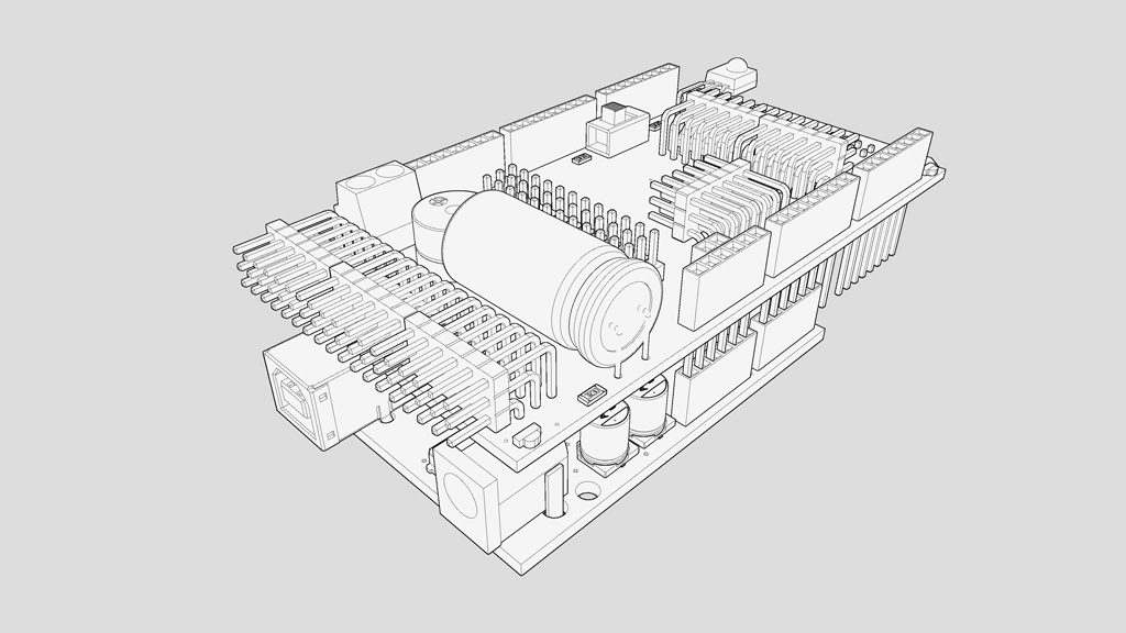
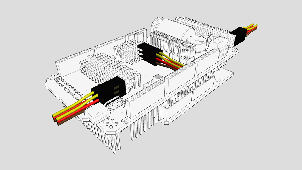
The VRSSM SHIELD allows you to connect 12 9G SERVO motors when the shield is plugged into an ARDUINO UNO and 36 9G SERVO motors when plugged into an ARDUINO MEGA. Instead of 9G SERVOmotors you can also connect sensors or other actuators. The VRSSM SHIELD can also receive an IR signal from the VR001 IR MODULE and has a beeper that you can program to make all kind of noises. There are also 4 blue LEDS on each corner of the board that indicate when the board is powered.
There are a few key points you need to be aware of when using the VRSSM SHIELD:
- Using the VRSSM SHIELD with ARDUINO UNO or ARDUINO MEGA
- Connecting a 9G SERVO the right way
- Understanding the shunts
- What does the PROGRAM / IR RECEIVE switch do
- What’s special about the SV1 port?
- A0 -> A5 connectors, what can they do?
- The external power connector
- Schematic of the VRSSM SHIELD
USING THE VRSSM SHIELD WITH ARDUINO UNO OR ARDUINO MEGA
You can plug the VRSSM SHIELD onto an ARDUINO UNO or an ARDUINO MEGA. The latter is a bit more powerful. You have to pay attention when plugging the shield onto the Arduino boards as damage can occur when it is not correctly done. Always plug and unplug the shields when the power is not connected! Use the images below as a reference.
ARDUINO UNO
ARDUINO MEGA
CONNECTING A 9G SERVO THE RIGHT WAY
When connecting a 9G SERVO to the VRSSM board you have to make sure you plug it in the right way. Each servo lead has 3 colored wires: YELLOW, RED and BROWN. Yellow is the signal wire, RED is +5V and BROWN is ground (GND). You can find the same identifications on the VRSSM SHIELD connectors (SIG, +, GND). To make it easier you can just remember that the yellow wire always has to be on top. You can use the image below as a reference.
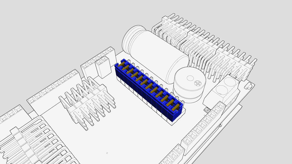
UNDERSTANDING THE SHUNTS
All the signal pins on the 9G servo connectors on the VRSSM SHIELD are connected to a pin on the ARDUINO UNO of the ARDUINO MEGA. On the ARDUINO UNO the relation is quite simple as you can only control a maximum of 12 9G SERVO motors:
UNO PINOUT: 9G SERVO 1 – 12 = PIN 1 – 12 on the ARDUINO UNO board.
On the ARDUINO MEGA it is possible to connect 36 9G SERVO motors. To free up the standard arduino pins (so you can use other shields when using an ARDUINO MEGA) we moved the 9G SERVOconnections when using an ARDUINO MEGA:
MEGA PINOUT: 9G SERVO 1 – 12 = PIN 22 – 33 on the ARDUINO MEGA board.
MEGA PINOUT: 9G SERVO 13 – 30 = PIN 34 – 51 on the ARDUINO MEGA board.
MEGA PINOUT: 9G SERVO 31 – 36 = PIN A0 – A5 on the ARDUINO MEGA board.
To make the switch for the first 12 9 SERVO motors you need to select the correct arduino board with the blue shunts as shown in the images below:
ARDUINO UNO

ARDUINO MEGA
WHAT DOES THE PROGRAM / IR RECEIVE SWITCH DO
The VRSSM SHIELD has a small switch, which let’s you choose between PROGRAM and IR RECEIVE. As the name implies, when you want to program the arduino when the VRSSM SHIELD is connected you will have to flip that switch to PROGRAM. If you do not do that the ARDUINO IDE will have trouble uploading your code. If you however want the robot to react to IR messages from the VR001 IR MODULE you will have to change the switch to IR RECEIVE (after you have loaded the correct code offcourse).
This is because the ARDUINO IDE uses the UART connection on the arduino boards and it is the same UART connection that is used when using the IR remote. Their is a small trade-off that you need to consider when setting that switch to IR RECEIVE but this will be explained in the next item below.
WHAT’S SPECIAL ABOUT THE SV1 PORT?
When the small switch on the VRSSM SHIELD has been set to IR RECEIVE the SV1 port is rendered unusable (when using AN ARDUINO UNO). This is an effect of the UART communication that is being used for the remote control. SV1 is connected to PIN 1 when using an ARDUINO UNO, but PIN 1 is also the TX pin for the UART communication, for the remote only the RX (PIN 0) is being used but by enabling the UART RX the TX is also not usable for servo control. You can use one of the A0 to A5 connectors as a replacement. When the switch is set to PROGRAM (and you cannot use the IR remove) SV1 is usable to control a servo. Also when using an ARDUINO MEGA SV1 is always usable even when using the IR remote.
A0 -> A5 CONNECTORS, WHAT CAN THEY DO?
These connectors can be used as normal servo controlling ports but they can also be used as analog inputs. This can be useful for sensors that you build yourself or that will be released in the future.
THE EXTERNAL POWER CONNECTOR
This power connector is connected to the servo power rail. You can use this to power the servos independently or you can use this to connect other actuators.
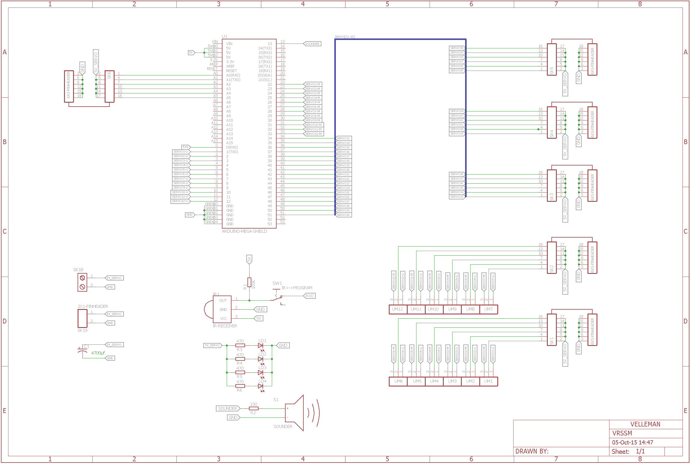
SCHEMATIC AND SILKSCREEN OF THE VRSSM SHIELD