Close
0%
0%

eForth for cheap STM8S gadgets

Turn cheap stuff from AliExpress into interactive development kits!

Similar projects worth following
Turn cheap STM8 µC boards into Forth development kits!

The code is based on Dr. C.H. Ting's interactive eForth for the STM8S Discovery, am STC Forth with Kernel, interpreter, and compiler in 5.5K Flash. I squeezed the interactive demo into 3.7K to get the most out of the 8K of an STM8S Value Line µC for $0.20.

Many features were added: Flash programming, Forth interrupt handlers, background task, vectored I/O, drivers for 7S-LED displays, analog and digital I/O, DO..LOOP, CREATE..DOES>... There is a simple framework for configuration, feature selection, support of new boards. and other STM8 µCs. Mixing C with Forth is possible, too, e.g. as a shell for testing, setting parameters, or for scripting.

Some HaD projects now use the STM8EF code. Check out the docs here and GitHub Wiki!

What is it good for?

The project delivers configurable board support code for selected targets, and docs. Besides its modest size, the TG9541/STM8EF code has a long feature list. Using the code for embedded control applications is subject to new projects.

The code on GitHub can be used in many ways:

  • for writing alternative firmware Chinese commodity boards (e.g. thermostats, DCDC converters, or relay boards)
  • for embedded systems with an interactive shell (scriptable and extensible)
  • for creating smart SPI, I2C, or RS232 smart sensors with a scripting shell, e.g. for RaspberryPi, Arduino, or ESP8266
  • as an interactive environment for exploring the STM8 architecture
  • for learning Forth. It's easy and fun - find out why in the text below!
  • ...

Why a Forth for Cheap Chinese boards?

Because it's fun: cheap mass-produced imperfection is a playground for creativity :-)

Right now, the W1209 is my favorite target: it's a rather complete embedded control board with a UI at a very good price. It's as cheap as it looks, and the challenge is in it's imperfections: the guy who designed the board clearly didn't have a connected application in mind, and I had a lot of fun making it do things it was never intended to do.

There are challenges, like the lack of communication ports. The "sensor connector" can either be used for communicating, or for sensing. What if you need sensing and communication at the same time? Maybe the "update connector" can be used as a home brew field bus interface? A lot is possible with the right idea, and the right software!

Which target boards are supported?

Besides generic CORE target for STM8S003F3P6, there is currently support for the following boards:

I also ordered the following SmartClima control boards for tests:

@Elliot Williams worked on using the ESP-14 as an IoT deviced (the ESP-14 is an ESP8266 with an STM8S003F3P6 in a ESP-12 package).

Programmable power supplies based on the XH-M188, and a cheap DC/DC converter are work in progress. There are also several types of STM8S003F3 based voltmeters that can be supported.

Read more about likely future targets below.

Why Forth?

Again, because it's fun!

Consider this:

  • compared to other programming environments the core of Forth is easy to fully understand
  • like Lisp, Forth has a REPL (Read-Evaluate-Print-Loop) which enables software testing in a way impossible with "Edit-Compile-Run-Debug" (e.g. Arduino)
  • it's easy to build Domain Specific Languages (you can literally program the compiler!)
  • the stack-centered "factoring" approach provides implicit data flow which leads to maintainable code
  • Interpreter-compiler, basic OS functions fit in just 4K code :-)

Forth starts out as a stack machine with a tiny instruction set and minimal hardware requirements. It fits in a few KiB, and the target, even a lowly µC, can even be used as the development system. The Forth stack machine is a minimalistic VM on a standard CPU, but there are also hardware implementations (e.g. for FPGAs, or a 144 core Forth processor). The VM is ideal for fast context switching and Forth easily meets hard-real-time requirements. It's no surprise that Forth was used in many NASA projects.

A Forth programmer is in control of all levels of problem abstraction, a unique advantage in a world where layer on layer of 2nd hand solutions leads to ever growing complexity (compilers, libraries, operating systems, drivers,frameworks, IDEs... ). I'm convinced that "Thinking Forth" will make anybody a better programmer, not just in the domain of embedded control!

Why STM8S003F3 or STM8S103F3?

Low-end "STM8S Value Line" STM8 µCs are very cheap (less than $0.25 in hobby quantities, $0.20@100pcs)....

Read more »

stm8ef_v2.2.0.zip

The latest release is on GitHub. Release v2.2.0

Zip Archive - 18.94 kB - 12/04/2016 at 23:22

Download

2157_stm8ef.zip

Original version of STM8EFalong with docs as received from Dr. C.H. Ting on 21/Nov/2016. The docs are worth reading, the eForth binary will run on the STM8S Discovery.

Zip Archive - 21.97 kB - 11/21/2016 at 20:13

Download

  • 1 × ST-Link V2 ICP adapter (e.g. $2.00 from AliExpress) The ST-Link on an STM8S Discovery Board can be used, too
  • 1 × serial interface /w 3.3V level (e.g. a $0.60 CH340 USB adapter) e.g a CH340 USB interface
  • 1 × STM8S target device as listed in the GitHub Wiki (e.g. a $0.70 "STM8S103F3P6 minimal system board") e.g. "STM8S103F3P6 STM8S development board" from your favorite China source
  • 1 × Some headers, patchwires, breadboard etc (about $2.00)

  • Release v2.2.11: Board XH-M188, ALIAS Feature

    Thomas06/04/2017 at 12:09 0 comments

    Board XH-M188 (Issue #29)

    @Elliot Williams contributed initial support for the board XH-M188. Thanks a bunch!

    After removing the socketed 7S-LED display the board offers a GPIO breakout, and standard RxD/TxD communication ports.

    ALIAS Feature (Issue #26, #27)

    @RigTig needs more free Flash memory for his main project. As Forth headers require a lot of memory he proposed loading Forth headers to RAM. With the help of some minor changes to forth.asm (e.g. enhanced NAME>) about 2000 bytes of Flash memory can recovered. Please refer to the discussion in #27.

    Words last and NAME> used in RECURSE example linked

    The recursive programming example requires last and NAME> to be exposed. That's fixed now.

    Binaries are here - Happy hacking!

  • Pushing the Limits: Beyond STC Forth

    Thomas05/28/2017 at 10:49 0 comments

    @RigTig has a very ambitious project: build a 3D printers for very large objects (e.g. a house) from almost nothing. STM8EF is a good match: it builds a programming environment for almost nothing (i.e. a STM8S003F3P6 µC). While the current code is already rather good, it needs to get better to meet RigTig's requirements.

    Issue #27 on GitHub discusses use case, requirement, and solutions:

    • Introduce assembler features
    • Extend the compiler (tail call optimization)
    • Introduce the ALIAS word class
    • Mix STC with DTC (using ALIAS words), or ITC (using a Inner Interpreter)
    • Malleable dictionaries
    • and more

    If Java is like coffee to make you type faster then Forth is like LSD which makes you see solutions in the fractal complexity of the universe!

    EDIT: RigTig used the alias method to create a lean-and-mean configuration for the W1209 board: it fits in about 3.5KiB code, almost 2KiB less than the normal W1209 variant, LED display code included!

    Check it out here.

  • Better Docs for the Relay-4 Board

    Thomas05/14/2017 at 17:47 0 comments

    The C0135 "Relay-4" board has 4 relays (duh), 4 inputs, and is based on the STM8S103F3P6 (the lower spec STM8S003F3P6 would have done the job just as well).

    I now updated the docs in the GitHub Wiki, and added some example Forth code that demonstrates how to use it as a heating / neutral / cooling temperature control (as if there wouldn't be enough Chinese STM8S003F3P6 based thermostats boards).

    By the way, right now this board is available on AliExpress for just $7.67, which isn't a bad price for a "Nano PLC.

  • Starting to work on the HC12

    Thomas05/01/2017 at 18:42 2 comments

    The HC12 is a Si4463 based RS232-RF modem in 433 ISM band. Compared with the average garage door remote RF solution the Si4463 is much more advanced (range, modulation modes, immunity to noise). It has so many features that the normal way to program it is to use a code generator provided by Silicon Labs, the manufacturer of the chip.

    The other chip on the board is an STM8S003F3P6, and that's why I write about it. Some time ago @ajlitt forked the STM8EF repository to work on the HC12. He did the reverse engineering, and wrote first code to make the STM8S talk to the Si4463 (a mix of board-support code, and Forth). However, he had planned to implement a packet radio protocol that needs more RAM than the STM8S has to offer.

    I have a much more humble use case: bring Forth into the STM8S of the HC12, and have it communicate with an off-the-shelf HC12 through the Si4463 radio.

    Some time ago I ordered 3 x HC12 modules that now have the following roles:

    • one with unmodified firmware connected a logic analyzer
    • one serving as development target
    • one with unmodified firmware as a reference

    The HC12 connected to the logic analyzer is necessary to understand, and re-implement the Si4463 API calls and parameters.

    I now implement the initialization, and the communication routines. There is an "issue", and some docs on GitHub.

  • W1701, the Ugly Duckling

    Thomas04/26/2017 at 15:21 0 comments

    The W1701 is a cheap thermostat that's designed as a "set-and-forget" temperature controller.

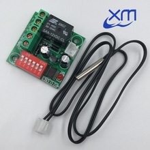
    At a price of $2.22 it's more expensive than the W1209 ($1.41), and only a bit cheaper than the surprisingly well designed W1401 ($2.48).

    The module comes without operating instructions - but that isn't the point - I wanted to find out if it can be used as cheap programmable control device. Of course it can be used (here are the details - if anybody needs code, please let me know), but it lacks the versatility of its more generously designed siblings, even if it's more expensive, and looks like it could be produced for less than $1. It's needless to say that it should never be used for high voltage.

    The W1701 is an ugly duckling that won't turn into a swan. I consider it a collector's item.

    EDIT: I just closed the "enhancement" issue on GitHub for W1701 board support with "won't fix". However, I also published some Forth code, and a W1701 SWIMCOM binary with initialization, OUT!, and DIP. For collectors, or for those who really need a board that can be configured with DIP switches.

  • Reverse Circuit-Bending the W1209WK

    Thomas04/17/2017 at 21:52 0 comments

    I've had a nice new specimen of Chinese power-circuit-bending on my desk: the W1209WK. The schematics is a good demonstration of "what not to do with a µC and a LED", even more so than the venerable "DC/DC with Voltmeter".

    It was quite challenging to work around the worst quirks of the circuit, but the board is now documented, and there is preliminary board support.

  • 7S-LED example for W1401

    Thomas04/17/2017 at 13:28 0 comments

    In the last log entry I described a feature for number and text output on grouped (structured) 7S-LED displays. In this log entry I'd like to give an example of how easy presenting information is.

    The XH-W1401 module has a 7S-LED display grouped in 3 x 2 digits (yellow, large red, yellow). There is no decimal point, but that's a different story.

    The following code displays different types of information on the different sections:

    FILE
    : timer TIM 655 / ;
    : ain 5 ADC! ADC@ 100 1023 */ ;
    : show timer . ain . BKEY . CR ;
    HAND
    

    The word timer returns the 16 bit ticker value scaled to 0..99, and the word ain does the same for the analog input (on the sensor header). show displays the values of timer, ain, and the board key bitmap code from BKEY followed by a CR (new line).

    The following session demonstrates the feature:

    show 19 28 0
     ok
    ' show bg !
    

    Calling show directly sends the output to the console. Running the same word in the background displays the values of timer on the left red 7S-LED group, ain on the middle red LEDs, and the board key bitmap on the right yellow group.

  • Character output on structured 7S-LED displays [solved]

    Thomas04/13/2017 at 05:06 0 comments

    Board support code in TG9541/STM8EF has supported boards with 3 or 4 digit LED displays for several months now, and output of text (e.g. numbers) on a LED display is simple.

    However, since support for the W1401 was added, there are now devices with "structured" LED displays. With "structured" I mean different color, size, or grouped in rows or columns.

    Device
    Digits & Groups
    W1209 3dig red
    W1209WK 3dig red, 3dig blue in 2 rows
    W1219 3dig red, 3dig green in 2 rows
    W1401 2dig yellow, 2dig red (large), 2dig yellow in 3 columns

    As an application programmer I want character output to be simple, and I want the code to look the same no matter if it outputs to the console or to grouped digits of LED displays (that's also important for testing). In the future there might be devices with LCDs, or serial data output, and code should "just work".

    The easiest way to achieve that, is to use whitespace as some kind of "output element separator" ("." and ".R" should have the same effect). <CR> can act as "return to first element". Of course, this will make the code more complicated than simply spilling text over to the next digit, no matter where it is, but it will make writing applications a lot easier.

    If someone has a different idea how to do it, I'd like to hear about it!

    EDIT1: OK, since I didn't hear about it, I implemented a prototype. It works quite well, but an extra state is necessary to handle CR consistently (whitespace or CR should move to the next display group only once).

    EDIT2: I tested the feature on boards with 1, 2, and 3 display groups, and updated the W1219 and W1401 docs on GitHub. Output of numbers and character strings on grouped LED displays is now really easy!

  • More Thermostats? Most likely yes, but there is more in the queue.

    Thomas04/07/2017 at 05:31 0 comments

    I didn't forget the "cheap Value Line" part of this project, but reverse engineering a gadget takes some time, writing and testing board support code even more (especially if there are many constraints, like in the case of the W1401 or the DC/DC converter).

    The following boards are in the queue:

    • 3 thermostats: W1209WK, XH-W1219, and W1701
    • 2 cheap hackable voltmeters, both clearly designed by Chinese hacker-engineers (RX/TX available, unused ports broken out, etc)
    • 1 wireless serial link module: HC12 (SI4463 based)
    • 1 linear power supply: M188
    • 1 hackable PWM module with LED display

    The W1219, and the M188 might be the next boards to get a board folder, and a binary release. I'm open to requests, though :-).

    Edit: the is an interesting W1209 related report about serial interface problems. Maybe I'll have to change the default serial interface of that board. Issue contains a test binary using a board key instead of the analog sensor header.

  • Release v2.2.9: Support for STM8S Access Line Devices

    Thomas04/01/2017 at 12:37 9 comments

    For the STM8 mainstream family *STM8S), ST marketing defined different "classes" of devices:

    • STM8S00X: Value Line
    • STM8S10X: Access Line
    • STM8S20X: Performance Line

    The code in this project initially targeted the STM8S105C6, but it's now optimized for low-grade Valdue Line devices (the STM8S103F3 is essentially a Value Line device with better specs).

    I now have this STM8S105K4T6 devices on my desk:
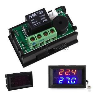
At about $1.90 it offers 16KiB Flash, 2KiB RAM, and 1KiB EEPROM, that's nothing to write home about. However, since the day when I started this project, I had the goal that the code isn't limited to a single STM8 variant. Now I have a target device for testing device configuration.

    EDIT1: the code in the develop branch contains the necessary changes for applying STM8EF to Access Line devices. The new include file target.inc also provides board specific configuration options for the memory layout.

    EDIT2: I just released v2.2.9 which adds support for Access Line devices. I haven't seen many cheap Access Line gadgets out there, but it's a nice addition to the home-brew toolbox anyway.

View all 70 project logs

  • 1

    Get some cheap hardware (e.g. a STM8S103F3P6 breakout board for $0.65 and a ST-Link V2 dongle for $2). download the binary release, flash it, and have fun!

    If you like it, and you want to hack board support code for your favorite STM8China gadget, you need:

  • 2

    a Linux SDCC tool chain installation (installation instructions for SDCC & stm8flash are in the Wiki)

  • 3

    Clone the project on GitHub

View all 4 instructions

Enjoy this project?

Share

Discussions

RigTig wrote 02/27/2017 at 21:59 point

Thomas mentioned that a better file loader would be nice. Here is my attempt. Simple to start with, but obviously capable of being expanded with features later. It is in Python2 and runs from the command line of the host machine (mine is LinuxMint).

<code>

#!/usr/bin/env python2

import serial
import sys
import time

port = serial.Serial(
    port='/dev/ttyACM0',
    baudrate=9600,
    parity=serial.PARITY_NONE,
    stopbits=serial.STOPBITS_ONE,    
    bytesize=serial.EIGHTBITS,
    timeout=5)

if len(sys.argv) < 2:
    print('Usage %s ... [fileN]' % (sys.argv[0]))
    sys.exit()

def upload(path):
    with open(path) as source:
        for line in source.readlines():
            time.sleep(0.2)        
            line = line.strip()
            if not line: continue
            if len(line) > 64:
                raise 'Line is too long: %s' % (line)
            print('\n\rsending: ' + line)
            port.write(line)        
            port.write('\n\r')
            chin = ''
            response_buffer = []
            while chin <> '\v':
                response_buffer.append(chin)
                while port.inWaiting() > 0:
                    chin = port.read(1)
            response = ''.join(response_buffer)
            sys.stdout.write(response)

for path in sys.argv[1:]:
    print('Uploading %s' % path)
    upload(path)

</code>

Usage: Save this code as a file (say named loadserial.py) and change its permissions to be executable (just the lines in between the code tags). I put loadserial.py in my local /bin folder. Edit loadserial.py so the port matches what you use when using a terminal console to connect to STM8 machine.

WARNING: I've just noticed that the indentation was inconsistently displayed, and python is indentation sensitive. So be very careful with just copy-and-paste. I'll put a copy of it up on RigTig's Big 3d Printer project here on hackaday.io.

Either put FILE on first line of the file to be sent, or type it into a terminal console and close it, then use a local command line interface thus: <code>  filename file2send </code>. Enjoy!

  Are you sure? yes | no

Thomas wrote 02/27/2017 at 22:26 point

Hi RigTig, this is cool! Now the last reason not to learn Python (the haploid language, as I use to say) has gone. I'm going to need it in my job, anyway ;-)

PS: I just added the tag v2.2.8.1.snapshot, and this means that the binary size of CORE is below 4096 bytes, complete with the new "transparent" VARIABLE feature

  Are you sure? yes | no

Thomas wrote 03/04/2017 at 11:07 point

I just tried your loadserial.py script - the handshake seems to work, and compiling code to NVM is very fast compared to the "worst case delay" method!

However, I had to interrupt the script with ctrl-c after the transfer was finished. The reason was that my Forth code ended with "HAND", after which loadserial.py waited in vain for the handshake signal.

I can imagine that an improved uploader does the following:

* handle FILE and HAND (no need to include those in source file), or

* terminate transfer when the response is anything but the handshake character

The next thing on a programmer's wish list is a way for including source files (nested, of course). I can also imagine testing if "base code" has already been transferred, e.g. using some query-response between the Forth system and the uploader.

  Are you sure? yes | no

Thomas wrote 02/27/2017 at 22:26 point

Hi RigTig, this is cool! Now the last reason not to learn Python (the haploid language, as I use to say) has gone. I'm going to need it in my job, anyway ;-)

PS: I just added the tag v2.2.8.1.snapshot, and this means that the binary size of CORE is below 4096 bytes, complete with the new "transparent" VARIABLE feature

  Are you sure? yes | no

RigTig wrote 02/23/2017 at 05:44 point

Thanks Thomas for a great environment in which to have lots of fun. I needed VARIABLE to be defined in NVM, but to keep its data in RAM. Some variables need to change for every data line processed (megabytes of GCODE), so using NVM is just not going to cut it for real use. Besides NVM access is slow. So, here is my replacement definition for my project:

: variable create here , 2 $6e +! does> @ ;

Now, this works only in NVM mode, because it makes no sense to use it in RAM mode anyway. Besides the DOES> part would be wiped every COLD or restart. The magic address of $006E is the address of next available RAM when in NVM mode.

If you want to test after a restart or COLD, you need to adjust the address of next available RAM to be after the last used address by a variable. In my case, the last used address was $009e. Note that in RAM  mode, the address of next available RAM is at $006A. So, I typed

$a0 $6a !

and then initialised all variables and they just work. Now this hack is not for every project (obviously), but does show what can be done when a need arises. Enjoy!

  Are you sure? yes | no

Thomas wrote 02/23/2017 at 21:35 point

Hi RigTig! That's indeed a nice hack, and it is much along the lines of what I had planned.

I'd like to propose the following solution: 

1. some memory below the user dictionary in RAM shall be set aside by adjusting the reset value of USRCP
2. the next variable address for NVM routines shall be stored in the (new) variable USRVAR, which shall be initialized from USRCP
3. when switching from NVM to RAM the reset value of USRCP shall be set to the value of USRVAR

I'd like to check if it's possible to make VARIABLE work transparently in NVM and RAM mode. Most likely writing a different word is easier.

  Are you sure? yes | no

RigTig wrote 02/24/2017 at 04:09 point

Thanks for compliment. I haven't really tried to make VARIABLE work in both RAM and NVM, but I am sure it'd work. The key is just understanding that there is one level of indirection (address of value instead of value), so RAM variables use an extra 2 bytes over the non-indirect version. Nice to avoid wasting ram, but not really a show-stopper. Coding in assembler should be far more memory efficient than the Forth version, but it's the joy of Forth to be able to do these kinds of things at all (and optimise later when you find that it is really a good idea!).

A hard reset or even COLD needs to preserve the ram space needed by variables, but I prefer not to lock in a pre-determined limit on the number of variables. I also hate wasting valuable resources by committing them for just-in-case scenarios. 

So let's consider the use cases. Is there a need to support programming to NVM, then RAM, and back to NVM? If we say that all NVM variables need to be defined before RAM gets any code, is that reasonable? At least all the ram needed is in one block in this case. Probably a bit hard to communicate to programmers, and practically impossible to enforce.

Even if there is some code compiled into ram before or after NVM variables are created, the only thing needed is to set the ram space used for parsing commands to be above the last used ram for any variable. This happens anyway until COLD or hard reset. Maybe all that is needed is a persistent vector stored in NVM to be used instead of the $0080 for start of ram space for code and variables. Now the incentive is for the programmer not to waste space, so it becomes 'obvious' that defining all NVM variables before using ram for anything else is just better management of the limited ram. VARIABLE needs to update the persistent vector each time, based on current ram pointer. Variables defined in ram waste space after a COLD, but that might just be a price to pay (and is quite ok during interactive development, methinks). Mmm... and RESET needs to reset the vector to first available ram for code and variables back to its compilation default ($0080).

I am sure to have missed something in this ramble, but hey, that's what hacking is about isn't it? If I knew what I was doing, then it is not real hacking! And what other language allows you to play around with how the language itself works, so Go Forth.

  Are you sure? yes | no

Thomas wrote 02/24/2017 at 06:41 point

RigTig, we're on the same page :-) 

If you read me previous comment carefully you'll find that the "machine" needed for implementing is mainly coded in the difference between "the reset value of USRCP" and "USRCP" (there is one error though: point 2. should be "in the new variable USRVAR which shall be initialized from the reset value of USRCP"). 

One could argue that this means waste of RAM, but actually it's just a buffer for certain use cases. You already mentioned some uses cases, and how much they would "surprise Joe Programmer".

My model for the programming workflow is this:

1. start a session with COLD, reset, or flashing the µC

2. write some test code in RAM (i.e. do the things you'd normally do with the original STM8EF)

3. run COLD and set the stage (e.g. define helper words like here: https://github.com/TG9541/stm8ef/wiki/STM8S-eForth-Programming#low-level-interrupts-in-forth)
4. run NVM, define words, variables etc as you like

5. run RAM, make pointers to the newly defined words, and also to USRVAR persistent

6. return to 4. (write more persistent code) or to 2. (test your code, preferably automated)

Of course, the casual user may miss the finer parts of the "Stage/NVM/RAM/Test/COLD" cycle, but they will notice quickly that words defined in RAM can't be compiled-in (only interpreted) in NVM, and that code compiled in NVM is lost if they forget to run RAM.

As you pointed out, a certain coding style, like defining variables first, isn't difficult to get used to. Setting aside a small buffer (e.g. 32 bytes) as a variable space wouldn't be a big deal, and it would enable the "setting the stage" use case without the risk of immediately overwriting words like IVEC. It's of course also possible to cycle through the steps 2..6 more often (also as a part of the source code) , but a buffer would add some flexibility. In the extreme case (use many variables, use a huge stack), writing test code in RAM would suffer. But hey, when testing words one tests the units, not the whole program where the stack reaches its maximum size.

  Are you sure? yes | no

Thomas wrote 02/26/2017 at 09:35 point

@RigTig

Please have a look at this: https://github.com/TG9541/stm8ef/tree/variable

The new code has the features discussed above. The behavior of VARIABLE and ALLOT is transparent in NVM mode, and in most cases there is no need to manage RAM allocation. Only if one allocates more than 32 byte RAM in a session it's necessary to cycle through COLD before using variables newly defined in NVM mode.

Edit: preliminary documentation of the new feature is here: https://github.com/TG9541/stm8ef/issues/16#issuecomment-282547170

  Are you sure? yes | no

RigTig wrote 02/27/2017 at 01:08 point

Thomas, I have to say that your approach is just brilliant. I love the idea of being able to just get more variable space if needed, and not wasting any ram either. 

P.S. We might be both on the same page, but I'm only partway down. I am still getting my head around the STM8EF code. I keep going back and changing the options for a new flash image and it is installed in a second or two. What fun to play with!

  Are you sure? yes | no

Thomas wrote 02/27/2017 at 07:17 point

@RigTig: thanks for your support! I just pushed a "size reduced" revision to the variable branch. Since I had to do some shuffling, some "review" and "testing" by "an independent person" would be great (in a hobby project that's what's known as "playing with the code" :-)

Currently some RAM gets wasted, but that could be bettered by giving the programmer control over the headroom for RAM allocation (which would be easy).

By the way, I ordered two of the radio modules you've been working on.

  Are you sure? yes | no

Elliot Williams wrote 01/23/2017 at 08:55 point

Hiya Thomas,

Got an ESP-14-powered device up and running and installed in our basement.  Long story, must write up.

Have you played around with power saving modes on the STM8?  I'm trying to get the part into the AWU / active-halt mode.  

For one, I need the assembler's HALT command, which I've been doing in the worst brute-force means possible: HERE $8e81 , EXECUTE.  (That's HALT and RET in machine code.)  

It halts, at least.  :)  

Coming back out of halt is messy -- it looks like the clocks aren't returned to their original states and so on. I'm probably going to need to implement some start-up code.  Heck, for my purposes, hooking into COLD for a complete reset will work too... That's what I'll try next.

Just wondering if you've worked on any of the low-power modes.  Either WFI (wait-for-interrupt) or the active-halt/AWU look tasty.

  Are you sure? yes | no

Thomas wrote 01/23/2017 at 19:14 point

That's great :-)

The power saving modes (like the watchdog) still are on my "important things that I plan to do" list. You know, that's the list on the sheet after "new and exciting things I want to play with", which in turn comes after "bugs I must fix now".

Let's put it on the "important new features for pilot applications" list :-) 

What we need is:

* a word HALT that contains the HALT instructionknow

* a word SLEEP, that stops unnecessary interrupts (user defined, and application specific). This word should run HALT. When the execution continues right after HALT, SLEEP shall re-enable "waking" interrupts

* if required a word to restore clock settings (RM0016 mentions something in 10.2.2 and in 9.9.4 "Clock master switch register (CLK_SWR)", but right now I don't undertsand why the clock changes)

Do you plan to trigger a wake-up through console events? The simulated COM port should support this use case!

  Are you sure? yes | no

Thomas wrote 01/23/2017 at 19:45 point

I added the HALT word, and it works better than expected. Here is a demo with a blinky:

    : g tim 40 and 0= out! ; ok
    ' g bg ! ok
    HALT
The when I press enter after HALT the LED stops flashing. The "ok" after HALT appears after I press enter a second time.

  Are you sure? yes | no

Elliot Williams wrote 01/24/2017 at 11:52 point

Woot!  

re: clocks: I read something somewhere sometime about them needing a reset.  I can't find that anymore.  I may be crazy.  

I saw some other STM8 code (http://blog.mark-stevens.co.uk/2014/06/auto-wakeup-stm8s/) that runs the AWU without re-clocking, strongly suggesting that I'm crazy.

That code, though, makes it look like (if interrupts are enabled) the AWU reset lands in the AWU ISR, which is uninitialized ($0000) in the vector table at $800C.

I just ran your BG example above, and it halts, but never returns until hit with a hard reset. I wonder if your code is working b/c it NOPs off to the next ISR and you got lucky.  Or does it actually try to execute whatever's at $0000?

So: how do we set up ISRs in eForth?  (Or, how do you write bytes directly to flash?)

  Are you sure? yes | no

Thomas wrote 01/24/2017 at 19:23 point

TL;DR: the quick-fix: an AWU "driver" that does it all but I would prefer a Forth solution and this requires some design decisions.

Long version:

Due to limitations in the SDCC tool chain any interrupt must be declared in main.c. Writing ISR vectors to Flash might work, but it requires a good approach for registering (and unregistering) interrupts to be viable (I'm thinking of RESET). Also Forth VM context switching would have to be done before executing any Forth code.

Another approach would be a "catchall" interrupt handler for several interrupts that then redirects to Forth code. This has the advantage that the context switch can be handled in a uniform way, but the dispatching won't be very efficient (or again a lookup).

This brings us to the next problem: some interrupt sources require resetting some bit in some peripherals control register. Leaving that to user code is very error prone, and a "catchall" interrupt handler would have to do it for all possible sources or leave it to user code.

What do you feel about of a middle way?
* Interrupt handler declared in main.c
* basic handler code in assembler or c to do a context switch, and to clear the trigger source
* handler code in Forth registered through something like BG

A last point: how many concurrent "Forth code interrupts" can we allow?
* Level0 we have the console
* on Level1 is the BG interrupt
* on Level2 is TIM4 (for COM simulation)

I guess that some stuff like TIM4 shouldn't have to compete with other code (the current code is efficient as it gets). Most likely it's possible to drop the interrupt level in BG code to Level0, and use Level1 for Forth handlers without character-I/O. The latency would still be in the lower µs range.

  Are you sure? yes | no

Elliot Williams wrote 01/25/2017 at 12:43 point

How does the 'BOOT mechanism work?  If you could do placeholders for the various ISRs like that, the user could write their handler function and store its address in the right place?  That seems very Forthy to me.  <code>: awu-isr stuff ; ' awu-isr ISR_AWU ! </code> or something.  One of these functions / memory locations per IRQ and you'd be done?

On resetting the flags as you leave the ISR: I think that should be user code rather than bloating up the system with it.  Yeah, it's going to hang the system if you do it wrong.  If I could count the number of times I've pressed the reset button...

On context switching in ISRs:  I'm not sure I understand the full details.  Unlike C, there's not necessarily any context to switch?  If the ISR maintains stack balance then there's no need for any context?  Leave whatever's on the stack, and it'll still be there when the interrupt is done?

For me, personally, I'd just be stoked to have a pointer to an address that I could set to execute when the AWU IRQ fires.  The rest, I can handle in code, I hope. :)  (Assuming that the return from interrupt works right.)

  Are you sure? yes | no

Thomas wrote 01/25/2017 at 20:20 point

'BOOT is simple: it returns the address of the "Parameter" field (like DOVAR). To safe code I used it to get the address of the whole following table of initialization values for USR variables. After switching to "NVM" it's possible to simply overwrite all these values. There is a 2nd copy to restore these values, e.g. to "forget" user vocabulary in Flash memory with RESET.

Yes, the 'BOOT method can be used in for interrupts, too, but that would require one more level of indirection.

About context switching:

my first approach was to re-use the Data Stack, but I quickly learned that X isn't always a valid Data Stack Pointer: it does that at the start and the end of a word, but not always in between ("always" is a very important attribute when writing interrupt code). Before implementing the background task, I tried  to make sure that X always represents a valid stack pointer in all primitive words. However, I failed to get it working until I started using a 2nd Data Stack for the background task (which I didn't like since it appears wasteful). Later on, I applied coding techniques that use X for reducing code size. Of course, it's possible to re-factor the code. It would be interesting to compare other multi-tasking Forth implementations. 

I went in a different direction: In several refactoring rounds I removed the following variables entirely: TEMP, XTEMP, PROD1, PROD2, PROD3, CARRY, and I also made the I/O context leaner.

Now, for code without character I/O only YTEMP must be saved. Otherwise also BASE, PAD, and HLD must be taken into consideration. And, of course, we need a stack. One approach would be to have a floating "stack pad" to work around the "X!=TOS" problem.

I guess it will take some time to implement a full featured solution for Forth interrupt handlers.

A minimal solution might look like this:
* a word IVEC! to set an interrupt vector
* a word SAVEC to save the context
* a word RESTC to restore the context, ends with IRET

The application could then define a word in the following way:  

: handler SAVEC ( some stuff ) RESTC ;

 ' handler 1 IVEC! \ set the AWU interrupt handler

Now that I'm looking at it, this doesn't look too bad.

Edit: I made some corrections, added some details, and added one more option for a solution

  Are you sure? yes | no

Thomas wrote 01/25/2017 at 22:23 point

I added the solution above for testing to the develop branch. Due to the mentioned limitations it's currently necessary to initialize the interrupt to priority low (0:1) (it shares the data stack with the ticker).

I also changed TIM4 to prio "highest", which might allow to implement all user defined interrupts with priority "high" later on. This would then require 3 data stacks with the sizes normal (console), medium (background task) and small (interrupt handler).

  Are you sure? yes | no

Thomas wrote 01/26/2017 at 20:48 point

@Elliot Williams:

Here is a starting point for Forth code user interrupts and AWU usage:

  nvm

  : awuint savec awu_csr1 c@ drop restc ;

  ' awuint 1 ivec!

  : initawu 38 awu_apr c! 1 awu_tbr c! 16 awu_csr1 c! ;

  ram

When I run HALT with this code, it returns immediately. Since I didn't find the time to make sense of the AWU configuration, I simply took the AWU timing values from the page you mentioned before.

Please not that this currently only works when I run HALT from the console (I still need a solution for the Data Stack problem). Running HALT from the background task would change the contents of the first element on the stack (which would work if the stack were empty).

A quick fix here is to assume that X represents TOS when HALT is executed (which is the case), and skip initializing the stack. Please note that this only works for HALT, and not in the general case.

  Are you sure? yes | no

Thomas wrote 01/23/2017 at 21:51 point

Changes are in the develpp branch on GitHub. The 2.2.6.snapshot release contains new binaries :-)

  Are you sure? yes | no

Youlian Troyanov wrote 01/26/2017 at 04:51 point

please write your long story about esp-14 :)

  Are you sure? yes | no

Thomas wrote 01/27/2017 at 22:19 point

Elliot, in order to get a simple and practical solution, I now propose the following:

1) In RAM code IVEC! (its only used once for setting an interrupt handler

: IVEC! ( a n - -  ) 2* 2* $800A + ! ;

2) Implement HALT as a user word:

: HALT  ( -- ) [ $8E C, ] ;

3) Implement your interrupt handler using SAVEC and RESTC (make sure not to use more than 8 cells on stack)

This will work for any interrupt. Please make sure to change the interrupt down from highest to high.

  Are you sure? yes | no

jaromir.sukuba wrote 01/23/2017 at 05:17 point

Another tip for *possible* STM8 target http://www.ebay.com/itm/12V-DC-Multifunktionsrelais-PLC-Cycle-Timer-Timing-Delay-Relay-Switch-Module-/131648915593

I didn't buy this one, haven't seen the schematics, but to me it totally smells like it could have STM8 under the display. Googling for XK-001T-1 didn't bring much info, though.

  Are you sure? yes | no

Thomas wrote 01/23/2017 at 06:18 point

Yes, that's possible. In most cases one won't find any schematics, and also the XH-, XK, M- or B monikers aren't always used the same. There is a small list of modules that are very likely STM8S based in the Details Section of this project (in the section "How can I spot suitable boards?"). If there is any interest, I can publish a list with advertised properties and the "street price".
Edit: here is a link with a picture showing the PCB legend:
https://www.aliexpress.com/store/product/Free-shipping-XK-001T-1-DC12V-Time-relay-board-count-voltage-testing-cycle-time-vehicle-charging/1548016_32656999267.html
Based on the outline of the µC I would expect it's not STM8 but a STC15 based, a µC which I've seen several times on "timer" boards (MCS51-like http://www.stcmcu.com/datasheet/stc/STC-AD-PDF/STC15-English.pdf)

  Are you sure? yes | no

Elliot Williams wrote 12/13/2016 at 23:13 point

Got my ESP-14 up and running last week, and then got distracted.  :)

Short story: it's just a STM8 chip and an ESP8266, like it says on the package.  The TX/RX lines are internally connected, so I was running your Forth on the STM8 with the ESP8266 powered down, and running all manner of software on the ESP with the STM8 powered down.

Been thinking about how to use both at once. 

a) Jeelink is a nice transparent serial port over ESP8266, which would provide remote wireless development of the Forth system on the STM8.  The idea of telnetting over WiFi into an STM8 is funny enough that I'm definitely going to do this.

b) Since the serial port is the only way in to the ESP8266, and the STM8 has only that one hardware serial port, I suppose that bit-banged serial or I2C/SPI could be used to talk to the console. I don't know how hard/easy this is. But then you'd have an STM8 that could issue AT WiFi commands, for instance, or run routines in NodeMCU, which might be very cool.

c) The other option is to code up the ESP and STM8 to take turns based on control characters: 0xFE toggles the ESP on/off the line, and 0xFF toggles the STM8, for instance.   This requires modifying _both_ firmwares, but would allow for the console, ESP, and STM8 to share the UART lines and talk to each other.

Just brainstorming so far. No real hacking yet. 

The breakout board I made for the module just fit it onto a breadboard, because I didn't really know what to expect from the module. It will probably want a transistor so that the STM8 can turn off the ESP8266 for power-saving when necessary, and will certainly want at least a jumper for flashing the ESP.  

Thanks for the case insensitive addition, and for do loops! This is a fun system to play around with.

  Are you sure? yes | no

Thomas wrote 12/14/2016 at 19:31 point

Options a) and b) look good to me, especially in combination. How about connecting a PNP transistor for the ESP8266 power supply to PD1/SWIM? Normally one would access the STM8 serial port through ESP-Link, and the ICP interface could be used for direct access to the ESP8266 serial interface by simply pulling down both NRST and PD1/SWIM. Direct serial access to the STM8 could be acchieved by telling it to power the ESP8266 down (this might even work using PD1/SWIM once more, e.g. by using an RC element which can be detected testing its timing).

Option c) would also be possible, but at least one of the devices would have to be able to swap RxD and TxD, and the other devices would need a "tristate" mode on TxD. The Bus approach I took for the W1209 might also work for more than two devices.

A fourth option could be to have a Forth word that issues the initialization AT commands on the STM8, and execute it with 'BOOT.

I hope to find the time for some hardware hacking in the holiday season :-)

  Are you sure? yes | no

Elliot Williams wrote 12/16/2016 at 21:22 point

"esp-link" not jeelink.  https://github.com/jeelabs/esp-link  Tried it and had a telnet / web-console controllable STM8 running your Forth.  Took like 10 minutes.

Then I spent 3 hours trying to implement something like c) in NodeMCU.

First, I thought I'd set up two TCP connections: one for the ESP to be executed locally, and one to pass through to the STM8.  Didn't work b/c NodeMCU can only do one TCP connection, it seems.

Then I thought I'd use MQTT as the transport mechanism.  But there's some glitch there with MQTT and the UART port not working right.  I'll hack more at it before I give up, but it might be time to move on to MicroPython or ESP Basic for the interactive ESP part.

Anyway, try out the esp-link for the ESP when you get around to it.  It's kinda fun.  It _does_ however leave me wanting a more capable microchip on the remote end.  For another couple bucks, I could get a lot more flash, peripherals, and etc to tether to the ESP.

All of this playing around has helped me refine what's needed in a breakout board for this thing, though.  :)

  Are you sure? yes | no

Thomas wrote 12/16/2016 at 22:35 point

Again great news, and I'm going to test esp-link too. Multiplexing communication through MQTT topics was the first thing that came to my mind. About a year ago I tried working with MQTT and NodeMCU, but I was disappointed with the stability of the platform (though I really liked working with Lua).
I guess that the case for ESP-14 is rather thin: as I mentioned before, it looks more like proof that the ESP8266 wasn't able to meet customer requirements than like the solution the world's been waiting for. But who cares as long as it's fun hacking.
In my opinion, a decent Forth environment on the ESP8266 would be rather attractive: C.H. Ting hacked something recently, but it was just the kernel, not a complete framework with persistent vocabulary (and maybe even with source stored in the Flash memory, and maybe even a JavaScript based IDE served from an embedded web server on the chip).

  Are you sure? yes | no

Thomas wrote 11/28/2016 at 21:33 point

Hi Elliot, it's great to hear that someone got it running, and that the docs were good for a smooth start. Anyhow, congrats for the "STM8EF Blinky"! Did you try to do that BG style, too? 

I had a look at the CAPS issue (yes, I've been thinking about that for a while ;-) ). There are some potential clashes (e.g. PARSE/parse, NEXT,next, ABORT"/abort") but the lowercase words are the hidden "implementation part", and I don't see that their name is set in stone. I decided to name them after their assembly labels (pars, donxt, and aborq). 

New code with lowercase support is on GitHub (just set CASEINSENSITIVE = 1 in globconf.inc). If you'd like to give it a try without building, please let me know (I can drop a binary into the files section here). If there are no issues I'll make it the default.

The ESP-14 will be one of my next targets. However, I didn't find the time to make a breakout PCBs with power supply for this module. Controlling the ESP8266 supply through the STM8S003F3 would be cool. If someone with good access to PCB prototyping could do that job I'd be more than happy to contribute some ideas about the schematics.

  Are you sure? yes | no

Elliot Williams wrote 11/29/2016 at 15:57 point

I just got an ESP-14 in the mail from ebay today.  I'll be making a breakout for it sometime in early Dec.  (Right now, I'm churning out HaD articles like mad.)  I'll share when I do.

I still have no idea if it makes any sense to run a (powerful) ESP8266 off of a (much smaller) STM8 chip.  But I'm willing to find out.  :)

I also ordered one of those LED/relay boards. Again, just for fun, but maybe I'll do something with it.

Thanks for thinking about caps.  I'll definitely rebuild and reflash. 

No, I didn't get into the multitasking / backgrounding. I just got the thing up and running, not much more.

  Are you sure? yes | no

Thomas wrote 11/29/2016 at 19:13 point

The ESP-14 is quite strange. I can only guess that an OEM required a solution from Espressif that meets non-functional constraints (e.g. dependability, power consumption, or periphery set) that could not be met by the ESP8266. I don't think that a lack of skilled programmers was the reason. The power consumption of the STM8S003F3 in "active halt mode" is quite low, and for a data logging sensor node a battery life of a year or more with a 100mAh battery might be feasible.

The W1209 boards are really fun, especially with a background task. When you try using STM8EF with it, please let me know if the docs for the single wire half-duplex solution are sufficient.

About the case-insensitive input: you're welcome (the option has a price tag with "23 bytes" on it :-) )

  Are you sure? yes | no

RigTig wrote 12/15/2016 at 10:44 point

I've created an adapter for ESP14 (and ESP12) to 22-pin DIL, if you haven't done anything else yet (see new project here called 'ESP-12 and ESP-14 adapter to DIL'). My ESP14s arrived today!

  Are you sure? yes | no

Elliot Williams wrote 11/28/2016 at 13:54 point

Hiya! Been following along, finally got a few minutes to flash stuff to one of those min-dev boards.  Great fun!  I haven't done anything useful with it yet, but I've gotten the LED blinking, naturally.

One thing that's driving me nuts is the ALL CAPS commands.  Is there an easy way to either a) lower-case them all or b) make it run case insensitively?  Or would that cause namespace clashes? It makes my shift-finger hurt. 

And that's it for now.  I have to say that your directions (combined with some of the links that you list) made it very easy to get up and running with the system.  Thanks!

I'm planning a few Forth columns for HaD, and I'm still collecting chips that have working implementations.  You've added one more to the list. 

Oh, and I've ordered an ESP-14.  We'll see how that goes.  Looks like fun. 

  Are you sure? yes | no

Similar Projects

Does this project spark your interest?

Become a member to follow this project and never miss any updates