
A Prusa i3 design running on Open Build's mini V wheels
The BldrBot uses Open Builds V-Slot technology. The framing utilizes one 20x80 extrusion for the base frame piece, two 20x40 extrusions for Z Axis uprights, two 20x20 extrusions for the Y Axis mini V wheels, a 20x20 extrusion for the X Axis mini V wheels, and a 20x20 extrusion for the top brace/handle. The X & Y Axises use the Open Builds mini V wheels for guide control. The build plate for the hot bed is from Open Builds also.
The BldrBot was tested using a PrintrBoard Rev D controller. The controller has been removed from the printer and will be replaced with an Azteeg X5 when Panucatt begins shipping after the Azteeg X5 kickstarter campaign. The Azteeg is simpler to wire-up and runs 1/32 micro-stepping on a 32 bit processor - a controller capable of running a precision, high speed, machine (compared to the common 1/16 microstepping on an 8 bit processor).
The BldrBot ran speeds, accuracy and layer thickness equal to an Ord Bot Hadron. Like the Hadron, BldrBot is silent running (the power unit is the only sound). The BldrBot is much more compact than the Hadron, making the BldrBot an easily portable machine.
Comparison: BldrBot; Printer width 16", Printer depth 16", Printer height 13.5", Build area 8"x8"x5.5". Hadron; Printer width 19", Printer depth 19", Printer height 15.5", Build area 8"x8"x5.5".
The BldrBot uses a modified QU-BD MBE v9 extruder that prints PLA/ABS plastic - in fact all of the green plastic in the pictures is PLA and was printed with this modified extruder. As sold by QU-BD, the MBE normally cannot print PLA plastic.
![[IMG]](../../../prntrwrks.com/picts/17.jpg)
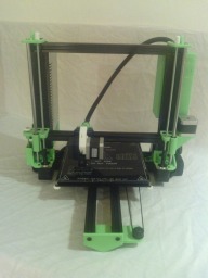
The Z Axis is guided on 8mm linear bearing bars, with 5mm threaded rods, a compact, proven i3 design. The X & Y Axises are running on Open Build's mini V wheels for silent operation and rigidity. Notice the two white, spring loaded, adjusting wheels on the front corners of the bed for bed leveling.
Front view with extruder carriage raised to top and heated bed all the way forward. Notice that the two Z Axis motors are Nema 14. All other motors are Nema 17.
![[IMG]](../../../prntrwrks.com/picts/37.jpg)
Close-up of the Prusa i3 Z Axis bearing brackets and motor brackets. Notice the white wheel on the right of the bracket for fine tune adjustment of the Z Axis height. The white wheel attached to the corner of the hot bed is used for bed leveling.
![[IMG]](../../../prntrwrks.com/picts/97.jpg)
Close-up of the extruder mounted to the min V wheels. The top mount bolts for the V wheels are also mounts for an extruder harness and end-stop bracket.
The spring loaded white arm on the extruder allows quick filament change while also forcing the filament to engage the MK7 driver gear on the motor spindle.
![[IMG]](../../../prntrwrks.com/picts/47.jpg)
Left view. The power supply and it's plugin box are mounted to the Z Axis upright (20x40 V-Slot extrusion). Wiring for the power unit, left Z Axis motor, Y Axis end-stop and heated bed are routed to the right side through the frame base piece (20x80 extrusion).
![[IMG]](../../../prntrwrks.com/picts/57.jpg)
Left view with X Axis carriage raised. Note the two top plastic brackets on the Z Axis uprights have guide holes for filament to pass through from a spool.
![[IMG]](../../../prntrwrks.com/picts/67.jpg)
Right view. The controller box is mounted to the Z Axis upright (20x40 V-Slot extrusion). Wiring harness from the left side, the X Axis motor and the Y Axis motor enter into the bottom of the controller box. The extruder harness enters into the top of the box.
The pulley below the X Axis motor drives a belt in the extrusion's horizontal v slots to move the extruder from side to side.
![[IMG]](../../../prntrwrks.com/picts/77.jpg)
Rear view showing the harness from the extruder entering the top of the controller box. A 40x40 fan is mounted in the center of the controller box. The fan is outboard to allow a filter to be mounted to it to prevent dust build-up on the controller board inside the box.
![[IMG]](../../../prntrwrks.com/picts/87.jpg)
Rear view close-up showing the off-set Y Axis drive set-up. The Y Axis mini V wheels run in the slotted grooves on the outside of the two 20x20 extrusions.
Notice the white adjustment wheel between the two Y Axis extrusion bars - that wheel adjusts the back height of the heated bed. By using the off-set drive set-up, the bed level can be adjusted on the three-point concept using two corner wheels on the bed front and this center one on the back.
BldrBot
Build in 'Cartesian Style Bots' published by Keith Davis, Mar 26, 2014.
A Prusa i3 design running on Open Build's mini V wheels
-
-
Build Author Keith Davis, Find all builds by Keith Davis
-
- Loading...
-
Build Details
- Build License:
-
- CC - Attribution NonCommercial - Share Alike - CC BY NC SA
Reason for this Build
The Open Builds V Slot and Mini V Wheels are a revolutionary break-through for creating compact 3D printer designs. Just what I had been looking for.Inspired by
Prusa i3 and Ord Bot Hadron.
![[IMG]](../../../prntrwrks.com/picts/27.jpg)
© XenZine Articles from Pick a Tutor