
June 21 2014: I am in the process of re-drawing the hardware to "as-Built" dimensions and appearance, plus there has been some travel, trade shows and conferences last week - progress should pick back up next week - James
Sections of this document will fall into the following 6 categories
Introduction
Documents
Structural
Mechanical
Electrical/Electronic
Software
Introduction:
I'll be adapting the existing 600x25mm mill to OpenBuilds and adding detail as it happens
The basic premise of the CubeSpawn builds is a goal of pure automation. Each cube is a frame with two bays:
The upper bay is a lightweight open Electronics/Electrical panel.
This is connected to the lower bay by a backplane.
The lower bay houses Mechanical/Robotics/Materials Handling equipment to give the cell its function.
This approach constrains the build area, but the design is intended to scale up by doubling, to a 1.2 meter cube, and beyond. For now, the 600mm size balances cost-to-prototype/capability i.e "big enough to make useful stuff, small enough to be affordable"
The Basic empty Cube consists of 5 electro/mechanical subsystems
Documents
- Cube Frame
- Electrical Tray & Rails
- Mechanical Tray & Rails
- Backplane
- Latches and connectors
BOM (Google-Spreadsheet) (updated 06/08/2014 10:40)
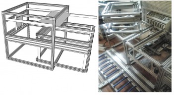
Structural
The frame is constructed of (12) 550mm pieces of 25mm tslot threaded M6 on both ends, I used 80/20 extrusion, but I understand Misumi costs somewhat less.
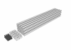
(click to enlarge)
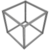
The (12) 550mm pieces are joined either with 25mm cube corners and 24 M6 bolts (I wasn't able to find any affordable 25mm cube corners, so I made some)

(click to enlarge)
However, if you do not have a mill, or access to one, you can use 24 brackets made from architectural 25x25mm aluminum angle, it does takes 48 bolts and 48 weld nuts to do it this way, but it can be useful to bootstrap a system and the hardware will recycle into subsequent builds.

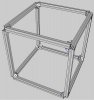
(click to enlarge)
The Upper electrical/electronics tray's rails are fashioned from aluminum angle, bolted directly to the t-slot of the frame.
The Lower, mechanical tray's rails are 25x75mm extrusion, mounted on centerline on 3 sides of the cube
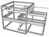
(click to enlarge)
The electrical tray carries either 1 or 2 aluminum panels (530x270mm) for mounted electric and digital devices. In the case of the Milling machine it will be 2, since the mill uses NEMA23 stepper motors, and therefore requires external motor drivers.
The mechanical tray has the working parts of the machine: motors, linear motion, spindle and pallet carrier. Other support cubes are a distinct possibility (Tool changer and magazine Cube, tool setter Cube, tool grinder Cube, etc.)
Mechanical
After careful evaluation, the Open Rail appears to be the best choice for conversion to the V-Wheel style motion. Its low width will mean a very slight increase in build envelope over the precision linear bearings used on the first build,
This is a very typical, Gantry style design
3D models for the build will be located in Trimble's 3D Warehouse
(Mill Build Pic Here)
Electrical/Electronic
Electrical distribution will be linear in these first machines, future plans are for a demand driven, managed, switched power network.
I'll be using two 48 volt, 10 amp power supplies, one for the motors, one for the spindle.
Why two? Two 10 amp power supplies run about $80, one 20 amp PSU is about $200...
I am open to suggestion on a better way to do this...
This will power the motors and spindle, but also the SBC (Single Board Computer) , A Raspberry-Pi in this case, but a BeagleBone or other SBC would work as well.
There is also a 4 port ethernet hub, This design used NEMA 23 motors so external motion control boards are required, end stops, lighting and any other accessories that may become available.
Software
All developed code will reside in CubeSpawn's Github. (I can use all the help I can get here!)
The on-board control stack is made for industry. An instance of Raspbian (debian for the R-Pi) runs ROS (the Robot Operating System) which provides a vast spectrum of capabilities to the machine.
Additionally; MTConnect, an inter-cube messaging process will be integrated into ROS, which runs on each cube. It provides a status based external interface to allow for semi autonomous machine to machine process coordination. the overall architecture and the underlying logic behind it is well explained in this video
Lastly, the ROS control architecture feeds g-code files to the SmoothieBoard.
Given the flexible nature of a Linux based SBC, I was able to get my system up and running without the ROS/MTConnect functionality for testing by installing Octoprint directly in Raspbian on the R-Pi and connecting it to the smoothie via USB.
A WiFi dongle in the R-Pi made the test rig portable. Octoprint's Smoothie aware, web-based printer interface made dropping a file and getting outputs a snap. On this build testing as to whether Octoprint can operate the mill will be explored, but the smoothie board can stream G-code so testing should not be too difficult.
New Diagram
CubeSpawn 3 Axis Mill Module
Build in 'Other Style CNC Mills' published by CubeSpawn, Jun 21, 2014 at 4:00 AM.
Small Form factor based 3 axis Gantry style mill, Removeable mechanical module. Removable Electronics. with a removable machine pallet, for automation.
-
-
Build Author CubeSpawn, Find all builds by CubeSpawn
-
- Loading...
-
Build Details
- Build License:
-
- CC - Attribution Share Alike - CC BY SA
Reason for this Build
It needs doing, All these stand-alone designs are great - but I want to build an object or device on my screen and retrieve a working copy from the output end of a manufacturing array - the logical consequence being the sooner you can do this, the faster it will accelerate...Inspired by
RepRap and many other projects

© XenZine Articles from Pick a Tutor