
.
.
.

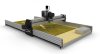
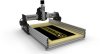
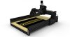
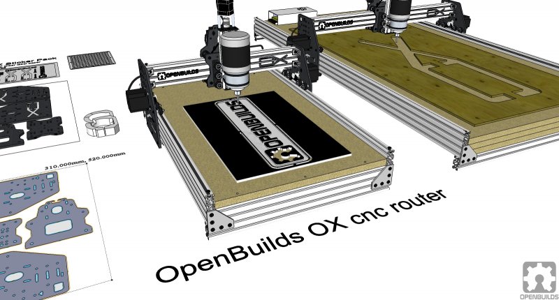
OpenBuilds OX
Open Source CNC Router Build
by Mark Carew
I have been working on a new CNC machine build I call the OX (because its strong)
It has been taking me some time because I am working on a build-along video as well as sourcing parts needed to complete the build. To be honest, I was going to wait before I released but I could not hold it back any longer
There are a lot of cool features this machine has but one of my favorites is that it can be built in a small format that will cut approx. 1' x 1.5' (310 x 480) to a large format OX that can cut approx. 2' x 4'! (580 x 1219)
'It's going to be a fun build that we are filming from the start to the finish so that anyone can follow along and build as well.'
The OX design is largely based on the ROUTY which is based on the Shapeoko cnc machine. I been learning a lot from the upgrades the guys on the forums have been working up (props go out to them) and wanted to incorporate them into a V-Slot machine, so the OX was born.
On an interesting side note - the ROUTY was used to cut the plates needed for the OX, so its machines making machines!
A note from the builder-
The OX build is complete with the exception of a few parts that will need to be updated as they are completed.
Part 1 video build of the OX
Frame assembly
Part 2 video build of the OX
Electronics/Software
Software Used:
SketchUp Make (Free)
SketchUcam (Free)
GRBL Controller (Free)
Belt & Lead Screw Calculator (Free)
Download more controller software to try out under the files tab
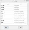
GRBL Settings (In the advance tab)
Your setting may/will differ depending on your setup. For instance if you are using MXL belt or more/less teeth on your pulley, different ACME lead screw or how many steps your drivers are set to drive your steppers at.
You need to use the Belt & Lead Screw Calculator to calculate what you need.
All this information can be entered into the calculator and it will give you a good starting point.
To get more precise results you will need to calibrate your machine by stepping it to a set distance and then measuring it.
Here are my settings using
Please note: The acme threaded rod that I am using (in the video) is pretty unique and really should not be used for this application. Its suited more for high speed movement of a short run, but its what I had and its working. I have plans to upgrade this soon to a 8mm *4 lead soon.
- 1/8th step on my motors
- GT2(3mm) belts with 20 tooth pulleys
- 6mm acme with a 10mm lead.(moves 10mm with each full 360 degree revolution of the motor)
Experiment with these settings to find the best set up for your machine.
More info/support about the GRBL Controller can be found here:
http://zapmaker.org/projects/grbl-controller-3-0/
_________________________________________________________________________________
OX MODS
As you build a machine you learn areas that could be improved upon, and so below are a few mods and upgrades we have added to the OX build with more to come!
_________________________________________________________________________________
* Quick & Dirty Tool Mount(MOD)
Quick and Dirty Tool Mount Parts List:
- [2] 3 inch worm drive pipe clamps - Coming Soon to the Part Sore
- [4] Drop In Tee Nuts
- [4] Cast - 90 Degree Corner Bracket
- [4] M5 x 8mm screws
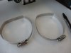
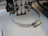
Note: The zip ties used in the video are replaced with the worm drive pipe straps as shown in the build pictures below.
New tool mount straps added
I was trying to figure out a way to make a stronger router mount. I knew a lot of the looseness was due to the zip ties, and they needed to be replaced. I wanted to use pipe strapping knowing that it could be tighten down, but could not figure out how to go about it.
The first plan was to drill holes in the corners brackets and feed the strapping through, but I did not really want to do this and mess up the corners. So as I am standing there thinking about it my brother comes in the shop looks at it and says why don't you replace these zip ties with pipe strapping - you could run them behind the corner brackets
I found out later that this is also the same way that Neil mounted his router on the Frog CNC build He did his this way before me, so I guess great minds think alike
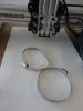
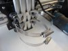
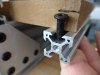
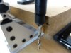
So the following pictures show (in order) how we went about it.
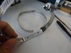
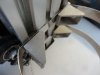
- First we flatten out one side of the strap
- Used the corners to help make the bends
- Mark the holes inline with the track
- Drill the holes with a 1/4" bit make sure to make them wider side to side so you have room for adjustments.
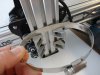
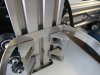
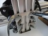
- Took the corners off (mark their spot on the rail first) added the strap between the drop in tee nut and corners
- Mount them back in the same spot (1-1/8" up from the bottom) Mount the second set as well.
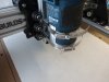
- Make sure your collet nut is just slightly lower then the Z axis plate
- Tighten down and add shims if needed to keep the router perpendicular with the z axis.
- Your done!
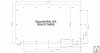
* OX Built Up Table Build (MOD)
Spoiler Board/Table
Built Up Table & Spoiler Board Parts List:
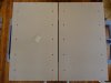
Making the spoiler-board
- [1] 17.5" x 29.5" - 3/4" MDF Board
- [6] Drop In Tee Nuts
- [8] Spring loaded (push-in) tee nuts
- [6] M5 x 15mm screws
- [1 pack] M5 x 8mm screws
- [4] Universal L brackets (Double)
- [4]Universal L brackets (Triple)
- [10] 1/4" ID washers (Coming Soon)
- [4] Hold down clamps (Coming Soon)
- [10] 1/4-20 hex bolts (knob style) (Coming Soon)
- [10] Threaded tee nuts (hammer in)(Coming Soon)
- [1 pack] Standard tee nuts
- [1] 20 x 40 - 1000 V-Slot
- [1] 20 x 80 - 1000 V-Slot
Lets make a simple spoiler board that we can use for cutting into when we are cutting a part out and the bit needs to go all the way though the material.
This board will also have 1/4-20 hold down clamps on the sides to allow for multiple material sizes to be clamped in place while being milled.
Note: On my board (shown in the pictures) I made the side 1/4-20 clamp hold down holes too close to the work area, the included dimensional drawing has the proper spacings so you would want to use that for your layout.
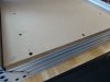
The following pictures will give you an idea on how we built our spoiler board for the OX
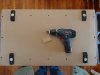
- Go to your local hardware store and get some 3/4" MDF cut to 17.5" x 29.5" (I had a 4'x8' sheet cut down to 5 of them)
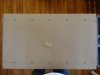
- Study the drawing and mark out all the holes to be added as shown(be sure to get the front and back board to V-Slot mounting holes lined up, they can be a bugger later on.)
- Drill out the holes. (Side holes (hold down's) are drilled to 5/16" front and back holes (board to V-Slot mount) are drilled to 1/4")
- Use a sanding block to knock off any excess and sand smooth
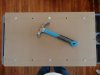
- While at the hardware store be sure to pick up some (hammer in) 1/4-20 x 5/16 threaded tee nuts (10 of them,I messed up and only got 6)
- Also pick up some 1 1/2" x 1/4-20 hex cap bolts(10) and 1/4"ID x 7/8"OD washers (10)
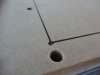
- Hammer the threaded tee nuts in (Tip: you may want to squirt a little glue underneath before the last hit in so they stay in place) (Also very important to make sure they are straight. The slightest angle can make them very hard to thread the hold down screw from the top)
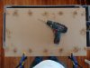
- Flip the board and screw in the hold down clamps tighten them down to help seat everything straight
- (These are prototype clamp plates that will be added to the Part Store once they are available)
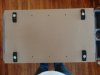
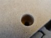
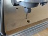
- Now to work on the front and back board mounting holes there are 3 in the front and 3 in the back of the board.
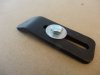
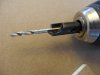
- Take a piece of V-Slot and a 15mm low profile screw hold the screw in the track and make a mark about 1/16" above the head of the screw. (This mark will tell us how far down to make the recess for the screw head, while not letting the screw bottom out on the V-Slot track.)
- Make a mark on your recessing bit so you know how deep to go. (Your recessing bit needs to have a big enough diameter to allow for the head of the screw (10mm or 7/16") to go into the recess)
- Recess the front and back holes down to the mark made on the recess bit and then sand the holes smooth
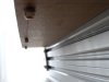
- Put in your 15mm screws and add drop in tee nuts to the bottom (only do a turn or two and make sure they are aligned to fit in the track)
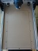
- Install the board to the V-Slot frame (Tip: This is going to take some fiddling and depending on how well you did on lining up your holes to the center of the track its tough to get these in. You may need to ream out the holes a little to allow for some movement to get these right. Also you will need to press down as you tighten the drop in tee nuts to ensure they can turn 90 degrees and catch the inside lip of the track)
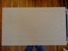
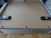
- Ok the spoiler board is in!
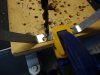
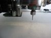
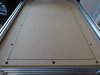
- Now lets find the maximum cutting area for the machine by moving the gantry's (by hand) to all four corners maximum movement and lowering the bit the spoiler, turning on the router for a sec to make a mark.
- Once you have all four marks set you can connect the marks with a straight edge and a marker. This safe cutting area will let you know where you can set your material for cutting.
- That's it. You're done and ready to hold down some material for cutting
Note: When you are setting up your cuts be sure to remember to stay on the inside of the clamps! you don't want to run into them.
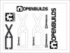
* OX Stickers (MOD)
- Grab the OX stickers jpg image file from the files tab above
- Print out at full screen on Avery full-sheet clear label paper #18665
- Cut the Stickers out and place them on the OX using the pics as a reference.
_________________________________________________________________________________
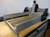
Reference Pics
V Carve Demo Video

OpenBuilds OX CNC Machine
Build in 'Cartesian Style CNC' published by kram242, Jun 12, 2014.
OpenBuilds OX CNC Machine. A strong easy to build shop CNC router that can be sized to suit your needs. Many new features have been incorporated into the OX to make it a great router that is sure to inspire!
-
-
Build Author kram242, Find all builds by kram242
-
- Loading...
-
Build Details
- Build License:
-
- CC - Attribution Share Alike - CC BY SA
Reason for this Build
We wanted a strong router for the shop that can be upgraded to a large r size if and when we need it.Inspired by
ROUTY, Shapeoko guys,CNC Zone guys, Belt and Pinion System -
Parts list
Qty Part Name Part Link Comments 1 Nema 17 Stepper Motor http://openbuildspartstore.com/nema-17-stepper-motor/ Link This is the stepper for the Z axis 3 Nema 23 Stepper Motors http://openbuildspartstore.com/nema-23-stepper-motor/ Link These are the steppers for the X and Y axis 1 V-Slot 20x80mm (1500) http://openbuildspartstore.com/v-slot-20-x-80mm/ Link Cut in half (750) Sides 1 V-Slot 20x40mm (1500) http://openbuildspartstore.com/v-slot-20-x-40mm/ Link Center Table support (710) Back Brace (500) Z axis (180) 1 V-Slot 20x40mm (1000) http://openbuildspartstore.com/v-slot-20-x-40mm/ Link Cut in half (500) Front and Back table support 1 V-Slot 20x60mm (1000) http://openbuildspartstore.com/v-slot-20-x-60mm/ Link Cut in half (500) For the X axis beam (sandwiched together) 28 Solid V Wheel Kit http://openbuildspartstore.com/openbuilds-solid-v-wheel-kit/ Link Will not need the 25mm screws for this build, save them for another build. 8 Cast - 90 Degree Corner Bracket http://openbuildspartstore.com/cast-90-degree-corner-bracket... Link Used as braces from OX plates to V-Slot X axis beam 4 5 Hole 90 Degree Joining Plate http://openbuildspartstore.com/5-hole-90-degree-joining-plat... Link Used to hold all four corners of machine together 4 Universal L Brackets (Double) http://openbuildspartstore.com/universal-l-brackets/ Link These are used on the center 20x40 table support 3 Aluminum Spacers (1-1/2 inch) http://openbuildspartstore.com/aluminum-spacers/ Link These are for the Z axis nema 17 stepper to space it from the threaded rod plate 40 Precision Shim - 10x5x1mm http://openbuildspartstore.com/precision-shim-10x5x1mm/ Link Used on all solid wheel spacing. Check model and video - X axis has two being used for spacing 13 Eccentric Spacers http://openbuildspartstore.com/eccentric-spacers/ Link Check model and video for proper placement and use of these spacers 2 Threaded Rod Plate http://openbuildspartstore.com/threaded-rod-plate/ Link For Z axis 1 5mm x 8mm Flexible Coupling http://openbuildspartstore.com/5mm-8mm-flexible-coupling/ Link For Z axis 1 8mm Threaded Rod http://openbuildspartstore.com/8mm-metric-lead-screw/ Link 8 inch Length - For Z axis 2 Lock Collar (8mm) http://openbuildspartstore.com/lock-collar/ Link For Z axis lead screw 2 Bearing ID 8mm http://openbuildspartstore.com/688z-ball-bearing-8x16x5/ Link For Z axis 7 GT2 (3mm) Timing Belt http://openbuildspartstore.com/gt2-3mm-timing-belt-by-the-fo... Link 7 feet - For belt driven axis X and Y (may want to get a little extra in case you need it) 4 Socket Head Cap Screw M5 - 65mm http://www.mcmaster.com/#91290a270/=qdro90 Link For Y gantry double plate wheels 4 OX Plates Link Check Files tab for DXF plate files to have cut 1 Acme Nut Block 8mm http://openbuildspartstore.com/8mm-acme-nut-block/ Link For Z axis 3 GT2 (3mm)Timing Pulley - 20 tooth - 1/4 Inch Bore http://openbuildspartstore.com/gt3-aluminum-timing-pulley-20... Link For Nema 23 Belt and Pinion drives on X and Y Axis 1 3 Axis Driver Board https://synthetos.myshopify.com/products/gshield-v4-shapeoko... Link gShield v4 Shapeoko Bundle. You can also use other driver boards of your choice, check the threads to see what others are using. 2 Low Profile Screws - M5x15mm / 25 Pcs http://openbuildspartstore.com/low-profile-screws-m5/ Link 2 packs 2 Low Profile Screws - M5x30mm / 10 Pcs http://openbuildspartstore.com/low-profile-screws-m5/ Link 2 packs 1 Low Profile Screws - M5x 45mm / 10 Pcs http://openbuildspartstore.com/low-profile-screws-m5/ Link 1 pack 2 Low Profile Screws - M5 x 8mm / 25 Pcs http://openbuildspartstore.com/low-profile-screws-m5/ Link 2 packs 4 M3 Cap Head Screws - M3x45mm http://openbuildspartstore.com/m3-cap-head-screws/ Link Z axis stepper screws 12 Nylon Insert Hex Locknut 5mm http://openbuildspartstore.com/nylon-insert-hex-locknut-5mm/ Link For 90 corner bracket to plate and for 65mm screws 24 Tee Nuts - 25 Pcs http://openbuildspartstore.com/tee-nuts-25-pack/ Link 1 pack 12 Aluminum Spacers - 1/8th inch http://openbuildspartstore.com/aluminum-spacers/ Link These are used to space the stepper motors from the plates 1 12V/30A Power Supply http://openbuildspartstore.com/12v-30a-power-supply/ Link To power the driver board (No wire kit). Could also use 24V power supply as well 1 Wire Block http://www.mcmaster.com/#7618k613/=qdrzki Link For Y axis combined motors 1 40x40mm x 10 12v Cooling fan http://amzn.com/B000LB0M8S Link For cooling the driver board 1 AC Power Cable with Bare End http://openbuildspartstore.com/ac-power-cable-with-bare-end/ Link For the power supply 5 Power cable http://openbuildspartstore.com/16-2-project-wire/ Link 2 conductor 16 gauge power cable to power the driver board from the power supply (Need 5 feet, may want 6 feet to be safe) 2 Spacer Block (V-Slot) http://openbuildspartstore.com/spacer-block-v-slot/ Link Used to space the Z axis wheels 0 Link 0 Link -
Attached Files:
-


© XenZine Articles from Pick a Tutor