Welcome to OpenBuilds Community

Signup today and join in on the fun!

Sign Up

YAOR (Yet Another Openbuilds Router)

Discussion in 'CNC Mills/Routers' started by winand, May 30, 2014.
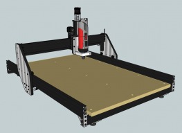
  1. winand

    winand Well-Known Builder

  2. kram242

    kram242 OpenBuilds Team Staff Member Builder

    Great looking build @winand love the look of the side plates! What kind of aluminum are you using? seems to be aluminum sheets with some other material (wood?) sandwiched in the center?
    Keep up the great work! :thumbsup:
  3. winand

    winand Well-Known Builder

    Jup, as you can read, it's a piece of 6mm MDF sandwiched between 2 sheets of 1,5mm aluminium, glued together with epoxy resin.
    After the epoxy hardened, the plates were cut on a bench saw en corners were rounded with a belt sander machine
  4. kram242

    kram242 OpenBuilds Team Staff Member Builder

    My fault I was quickly skimming through the build at work :D Thanks for the explanation seems like this would be a great rock solid light weight gantry.
  5. Tweakie

    Tweakie OpenBuilds Team Staff Member Builder

    Excellent work and a well detailed build @winand - The neatness of the wiring within your control box is especially impressive. :thumbsup:

    Tweakie.
  6. GrayUK

    GrayUK Veteran Builder

    I like the idea of the under-slung motors. I guess this would help in the flex department seeing as how the weight, and drive stress, would be transferred to below the pivot point. You know what I mean.

    I know I haven't read it through thoroughly, like Mark, but how much clearance is needed for the motors?

    Gray
  7. winand

    winand Well-Known Builder

    @Gray; I think that you mean how much height the Y axis motors take up under the 60x20 beam?
    This is about 6cm (2.36 inch) By turning the motor (Nema17) 45 degrees, the top mounting screw is exactly on the same height as the axles of the vslot wheels (could even get a little higher i think). You won't be able to achieve the same height with not turning the motors, the mounting holes of the motor would get in the way with the wheels.
  8. winand

    winand Well-Known Builder

    @Tweakie; Thanks! It was a tight fit to get al the parts in and make it a bit tidy, but it serves me well and tidyness helps for reliablilty :)
  9. GrayUK

    GrayUK Veteran Builder

    It is refreshing to see someone thinking "outside the box". Well it's new to me. :)

    Do you tension the Y Axis belt from beneath the Y member with the Reverse T nut? Have you found the One bolt holding the Y member to the front cross member is sufficient to keep the Y track upright and stable?
    [​IMG]
    Good Job
    Cheers
    Gray
  10. winand

    winand Well-Known Builder

    Nope, the hole in the front plate is just a hole where the excess belt sticks out and to grab it when tightning.
    To belt is clampt by a screw and a reversed t-nut which also holds the triangular bracket, it is not cranked down super tight because of the belt..
    The hand is pointing to the set screw:
    temp.jpg
  11. Jeferson SImoes

    Jeferson SImoes Well-Known Builder

    How do you cut the spacer for the motors? They are accurately with the same length?
  12. winand

    winand Well-Known Builder

    I cut them using a miter saw as accurate as possible.
    After that, i lined them up in a L-profile (so bottoms are lining up) and clamped them in a vice. Then i Filed them carefully to the same length using a hand file. Works surprisingly well.
    Jeferson SImoes likes this.
  13. winand

    winand Well-Known Builder

    Little add-on for my machine; a Z-axis touch plate.
    I mounted a 6,3mm jack socket on the gantry. The touch plate has a 6,3mm plug so i can plug it in when desired.
    It uses the Z- limit switch connection to the controller board. Works like a treat.
    IMG_1994.JPG
    IMG_1998.JPG
  14. dddman

    dddman Journeyman Builder

    @winand

    Where did you put your zmax (highest position) limit switch?
  15. winand

    winand Well-Known Builder

  16. GrayUK

    GrayUK Veteran Builder

    Winand. Hi.
    I see you opted for the Kress 1050. What made you go for it? I have pretty much made up my mind to get one. Did you go for the lower speed one?

    Cheers Gray
  17. winand

    winand Well-Known Builder

    Yes. i have the "1050 FME-1" (low speed) version. To date i did no extensive milling with it yet, so i can't tell you too much about it.
    I have read it's a stable router motor with very little play in the driveshafts bearings which makes it exellent for precise milling.
    I could have chosen to play with cheaper "Dremel" style drill grinders first but chose to invest a little more bucks right away.
    The Kress is easy to use (just need a wall socket, no separate VFD) and is relative cheap compared to a really professional setup.
    I think it's more useful to be able to use lower spindle speeds for some materials & bits.
    25.000 rpm at max would also be enough for virtual anything, the high speed version is 29.000 rpm max, so not that big of a difference.
    De minimum speed is however a big difference; 5000 against 10.000 rpm ..
  18. winand

    winand Well-Known Builder

    Little update;
    I moved the Y axis limit switches from the fixed table to the movable gantry. This way i have one bunch of cables, eliminating teh need for a splitting limit switch cable. DSC_0001 (3).JPG
    Added a lillte alu profile to protect the switches during moving of the machine;
    DSC_0003 (2).JPG
  19. winand

    winand Well-Known Builder

    I added a camera (endoscope type) on the Kress mounting block.
    I mounted it through a aluminium profile en fixed it with a simple screw, hoping it would be perfect aligned.
    Well, it's very usable, only when moving the Z-axis completely from top to bottom, de cross-hair moves a bit.
    Because you never know which type of bits you're gonna use this has to be adjusted. I'm thinking of a set screw
    to be to tilt the camera slightly (guess 0,5 degrees is already enough)

    DSC_0005 (3).JPG

    DSC_0007 (3).JPG
    kram242 likes this.
  20. GrayUK

    GrayUK Veteran Builder

    That looks cool! Is it really working for you? Again, I thought I might set myself up with a camera, it seems to make so much sense, especially when placing the job on the bed, and then defining it's position, as Tweakie did earlier, with a multi-point reference. Where did you get the camera from, and how much?

    Gray
  21. winand

    winand Well-Known Builder

    I did install the camera today, did not use it yet for real when milling. It can be very handy i think, but only if it is (and stays) accurate.
    Else you will find yourself checking the offset manually every time ;-)
    Second reason to add the camera is just for the fun of it, it is not that expensive too.
    I got the tip for an endoscope camera from Tweakie, discussing this following build:

    http://openbuilds.com/builds/tool-position-setting-part-iii.490/

    Note that Tweakie had to secure the sensor inside the camera housing with a bit of glue. I will soon find out if I'll have to do the same.

    I searched on eBay for "USB Endoscope Camera" and found a suitable one with an outside diameter of 10mm and a 5m cable for around 12 USD incl shipping.
  22. winand

    winand Well-Known Builder

    Today i have made my first PCB.. ever! :)
    A level bed is very important for milling PCB tracks, because you don't want to cut too deep.
    I have made a little adjustable bed especially for milling PCB's.
    Construction is dead simple; two pieces of MDF with 3 holes in them. (oversized holes in upper one allows pitching) In the bottom one 3 bolts are mounted (fixed). on the lower plane 3 little springs are attached (in this case holded snuggly into 3 under sized holes).
    3 bolts go on the bolts, upper plane, and again 3 bolts.
    IMG_2014.JPG

    This ables you to lower the Z-axis at 3 points (near the 3 bolts) 3 times at the same height, compressing the spring a little bit. The only thing you have to do is tighten the lower bolt and then the upper bolt.
    I used an "dome head" bolt screwed into a M6 hole in my kress mounting block, lowered my Z-axis only once and moved it around. The bed follows :)
    DSC_0001.JPG

    This really is my first try in milling a PCB, and the results are above satisfying i must say. When looking up close, it's still a little bit rough and the depth of the tracks seems not the same everywhere.
    (Note: When you're cutting not deep enough it's is simple to adjust the bed in one corner a little bit and run the program again, in this case that was not neccesary)

    I used a 0.2mm 30 degree carbide bit for all three stages (layout, holes, outside) because i'm still waiting for some other small bits to arrive by mail (just testing now really) Spindle speed about 20,000 rpm, feed rate 500 mm/min

    I set the depth of cut to 0.2mm for the tracks, 0,4mm for drilling (i know, not really a suitable bit for drilling ;-)) and went 1.4mm deep for the outside making the edged peel off easilly.

    IMG_2003.JPG

    IMG_2012.JPG

    Attached Files:

    Robert Hummel likes this.
  23. Robert Hummel

    Robert Hummel Custom Builder Staff Member Builder

    Well done ! :thumbsup:
  24. Tweakie

    Tweakie OpenBuilds Team Staff Member Builder

  25. kram242

    kram242 OpenBuilds Team Staff Member Builder

Share This Page