
OSH Park
Profile for 8n1
- You need to sign in or sign up before continuing.
Shared projects
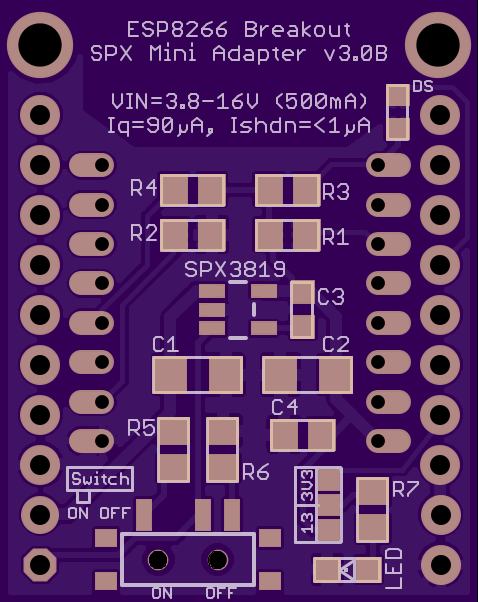
ESP8266 Breakout v3.0B - SPX3819 - Mini
by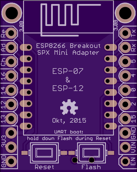
2
layer board of
0.96x1.21
inches
(24.28x30.61
mm).
Shared on
October 18th, 2015 16:02.
untested (not yet in production)
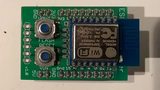
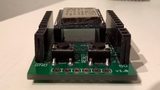
ESP-07 & ESP-12 Breakout Adapter with on-board voltage regulator - Version 3.0B
Used LDO: SPX3819 (Vin=3.7-16V, Dropout=340mV(-550mV), Iq=90µA)
Eagle files, Pictures, Schematic, Partlist(BOM)
https://github.com/8n1/ESP8266-Breakout-Adapter
ESP8266 Breakout v3.0A - AS1363 - Mini
by

2
layer board of
0.96x1.21
inches
(24.28x30.61
mm).
Shared on
October 18th, 2015 16:02.
untested (not yet in production)
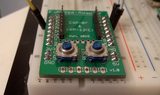
ESP-07 & ESP-12 Breakout Adapter with on-board voltage regulator - Version 3.0A
Used LDO: AS1363 (Vin=3.5-5.5V, Dropout=150mV(-320mV), Iq=40µA)
Eagle files, Pictures, Schematic, Partlist(BOM)
https://github.com/8n1/ESP8266-Breakout-Adapter
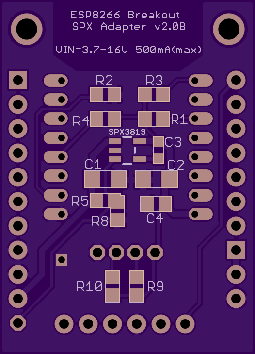
ESP8266 Breakout v2.0B - SPX3819 - TESTED
by
2
layer board of
1.05x1.46
inches
(26.72x37.06
mm).
Shared on
October 4th, 2015 20:27.
Documentation
https://github.com/8n1/ESP8266-Breakout-Adapter/blob/master/Breakout%20Adapter%20v2/README.md
ESP8266 Breakout v2.0A - UART Adapter [TESTED]
by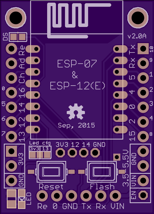

2
layer board of
1.05x1.46
inches
(26.72x37.06
mm).
Shared on
October 4th, 2015 20:27.
Documentation
https://github.com/8n1/ESP8266-Breakout-Adapter/blob/master/Breakout%20Adapter%20v2/README.md
ESP8266 Breakout Adapter
by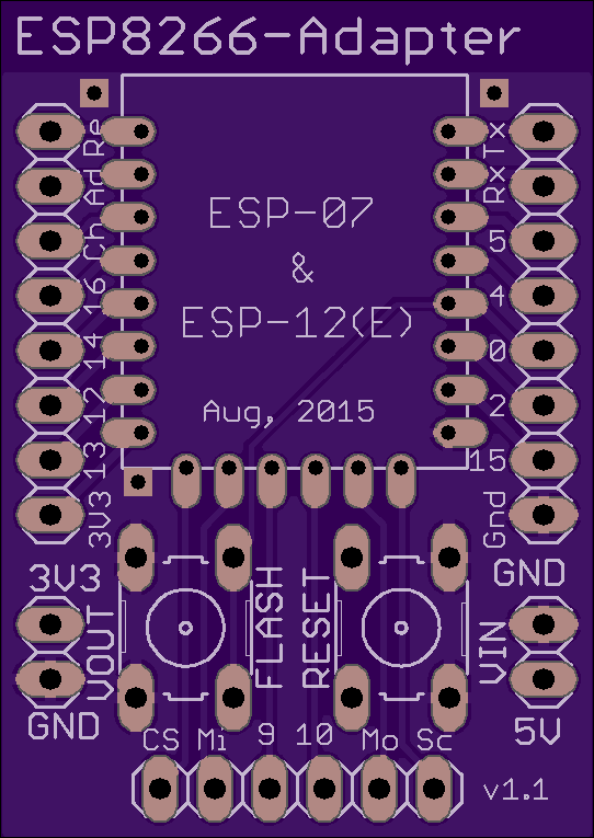
2
layer board of
1.08x1.53
inches
(27.48x38.84
mm).
Shared on
August 20th, 2015 01:45.
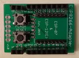
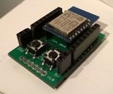
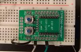
ESP-07 & ESP-12(E/F) Breakout Adapter with on-board voltage regulator
Pictures
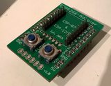
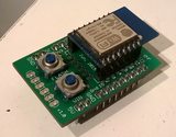
Full album: http://imgur.com/a/fsVE8
Schematic

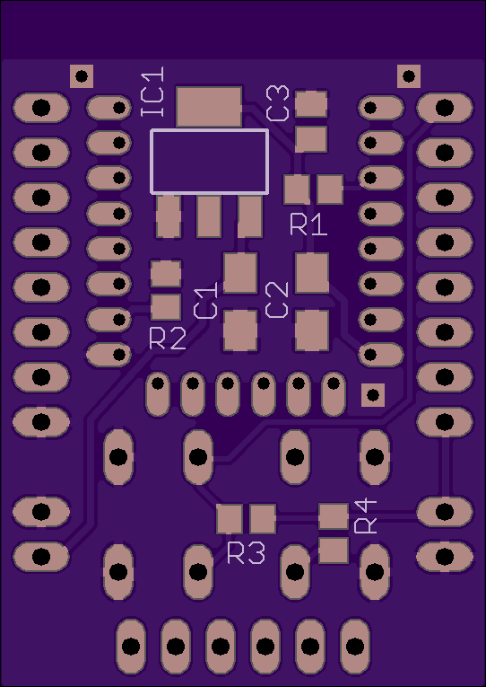
Features/BOM
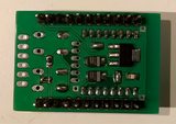
- x1117-3.3 voltage regulator (AMS1117, LM1117,…) - IC1 - [SOT-223]
- Input, output(C1, C2 - Tantalum 10µF [1206]) and decoupling capacitor(C3 - Ceramic 100nF [0805])
- Pullup resistors for CH_PD(R1), RESET(R3) and GPIO0(R4) - 10K [0805] *
- Pulldown resistor for GPIO15(R2 - 10K [0805]) *
- Reset button “tactile” (connects Reset to GND) - [THT]
- Flash button “tactile” (connects GPIO0 to GND) - [THT]
- ESP-12E pin header(bottom pins) **
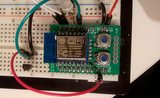
- Breadboard compatible (one row stays free on both sides)
* R1 and R2 could also be a solderbridge or 0 Ohm resistor if the “pulled” pin will not be used
** The additional bottom header on the ESP-12E can not be used without modifying the ESP module:
http://www.esp8266.com/viewtopic.php?f=32&t=4094
Note: The idle current consumption of the 1117 voltage regulator is about ~5mA!
More details
https://github.com/8n1/ESP8266-Breakout-Adapter/tree/master/Breakout%20Adapter%20v1.1%20-%20LM1117
License

Creative Commons Attribution 4.0 International
http://creativecommons.org/licenses/by/4.0/