
OSH Park
Profile for TelescopeLab
Shared projects
Astro Lamp 5 LED Head
by

2
layer board of
4.09x0.35
inches
(103.81x8.89
mm).
Shared on
December 7th, 2015 05:44.
Astronomy LED map lamp 5 LED linear head
5v (USB powered ) Astro Lamp LED Dimmer
by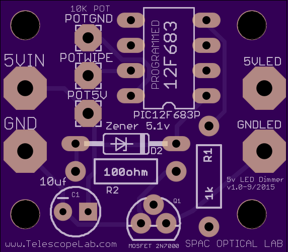
2
layer board of
1.14x1.00
inches
(28.91x25.40
mm).
Shared on
November 15th, 2015 00:19.
USB Powered Astronomy LED map lamp dimmer (PWM)
Astro Lamp 4 LED Head
by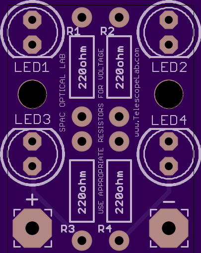

2
layer board of
0.75x1.00
inches
(19.05x25.43
mm).
Shared on
November 15th, 2015 00:18.
Astronomy LED map lamp LED head
9-12v Astro Lamp LED PWM Dimmer
by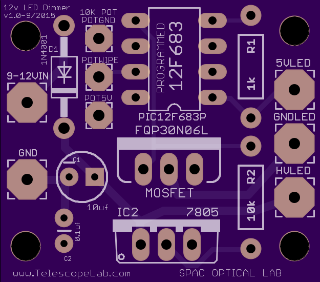
2
layer board of
1.25x1.10
inches
(31.78x27.94
mm).
Shared on
October 12th, 2015 03:11.
Astronomy LED map lamp dimmer (PWM)
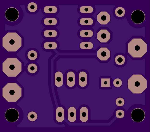
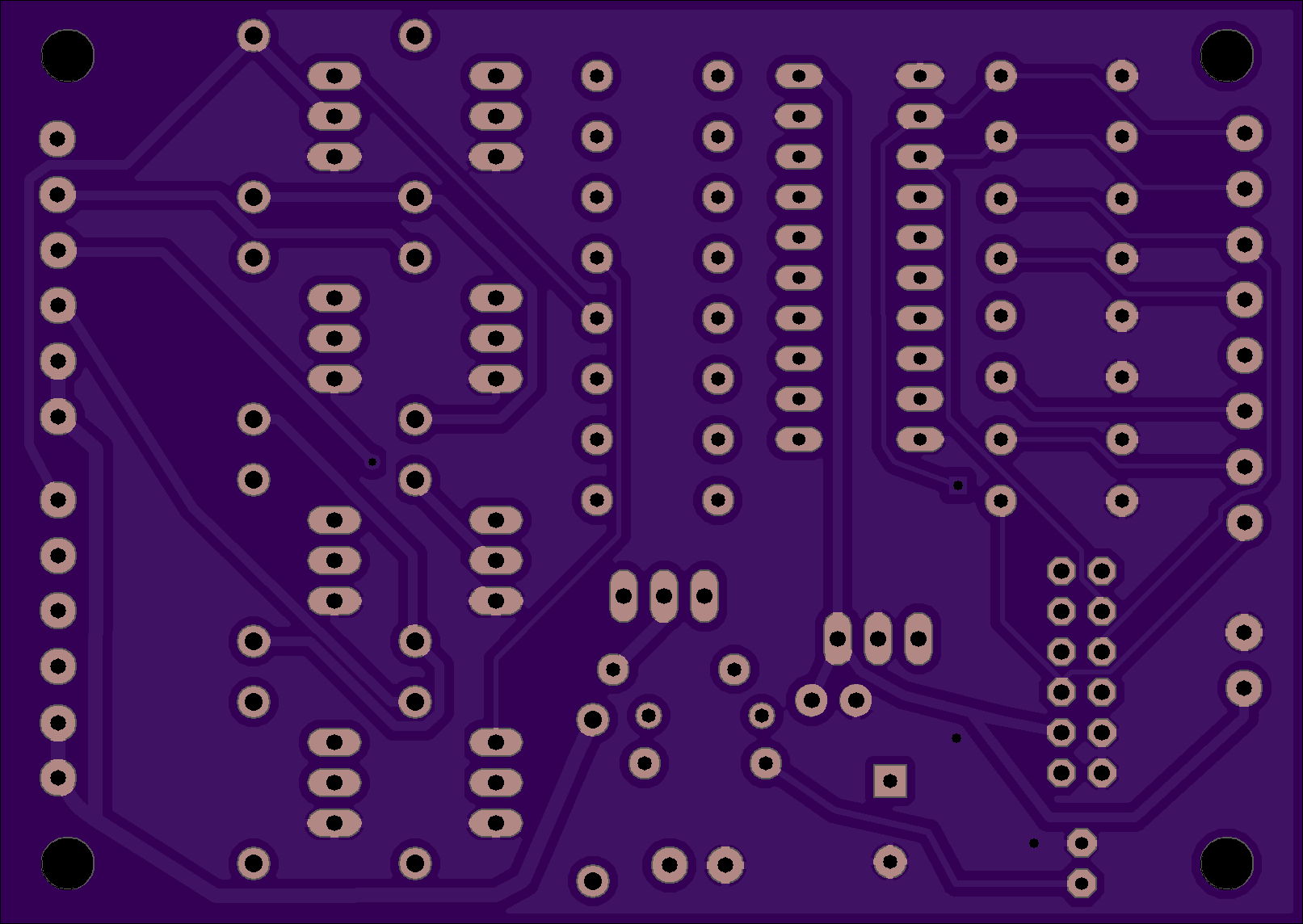
Robo Foucault Unipolar Stepper Controller
by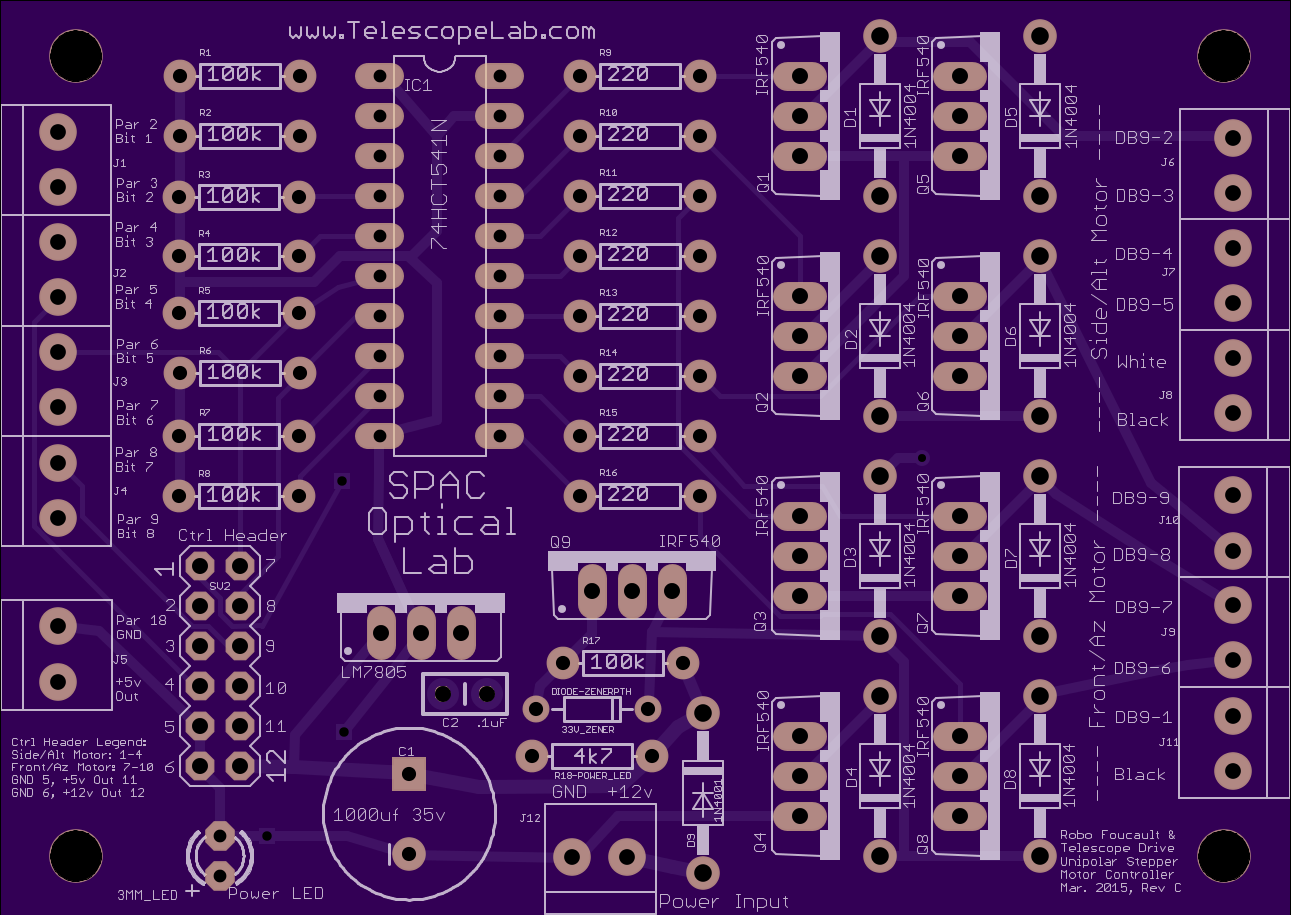
2
layer board of
3.22x2.29
inches
(81.89x58.09
mm).
Shared on
July 22nd, 2015 16:40.
Dual stepper motor controller for the James Lerch Robo Foucault Mirror Tester
Here’s a parts list (you still need two motors (Jameco #155433) for the platform, video capture board, appropriate camera and a Windows (XP and Vista tested) computer with a parallel port):
1 Robo Stepper Controller Circuit Board
1  20 pin soldertail socket
1  78HCT541 (or SN74HCT541N)
12 Terminal Blocks, Dual 3.5mm pitch (may omit is soldering wires to board)
9  100k 1/4 watt resistors
8  220ohm 1/4 watt resistors
1  4.7k resistor
9  IRF540 MOSFET
1  33v Zener diode
9  1N4001 Diodes
1  LM7805 5v voltage regulator
1  1000uF 35v electrolytic capacitor
1  0.1uF ceramic capacitor
1  Red LED, 3mm
1  2x6 straight header (only needed if using external control board)

1 Power supply, 12v at least 1.5A (1A is right at the limit)
1  Parallel port cable to connect the computer to the board.
1  An appropriate project box  (An external hard drive case with built in power supply may work - check amp output)
At the lab the board’s output goes to a DB9 socket (labeled on the board) and a old serial cable is used to connect that to the motors. As long as the correct motor wire goes to the correct board output the connectors are up to you. More info about the wiring is here