
OSH Park
Profile for strongeye
- You need to sign in or sign up before continuing.
Shared projects
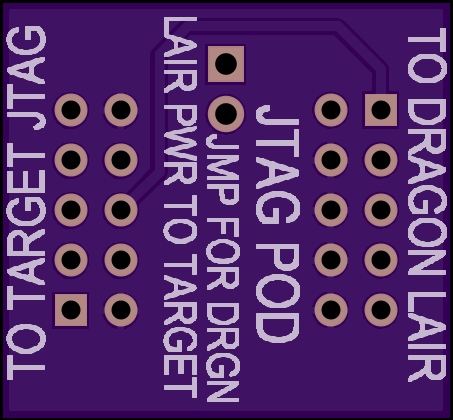
DRAGON LAIR JTAG CABLE POD
by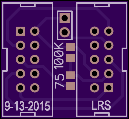
2
layer board of
0.91x0.84
inches
(23.01x21.36
mm).
Shared on
October 13th, 2015 16:56.
Descrambler for Dragon Lair JTAG output at Target end of JTAG cable.
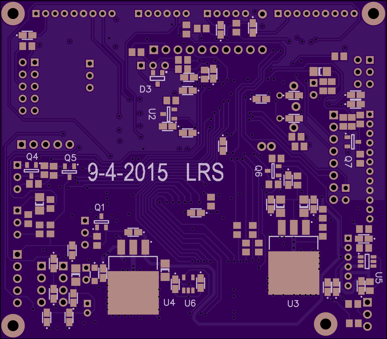
9XTX CONTROLLER
by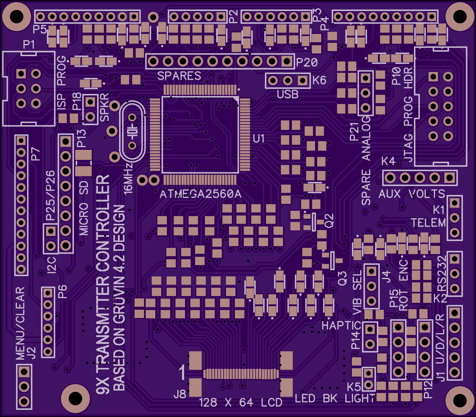
4
layer board of
3.21x2.81
inches
(81.43x71.27
mm).
Shared on
September 4th, 2015 22:20.
A 9X RC transmitter controller based on the Gruvin9X 4.2 design using an ATMEGA2560 MCU. This is a 4 layer ultra compact design to be retrofitted into almost any reasonably sized non-Turnigy/FlySky case. All 4 layers have copper planes for voltages and ground including a portion for Analog Ground. Extensive 0805 SMD components are used on both sides along with other SMD transistors and ICs. The slightly larger 0805 parts are easier to solder for most people than the 0603 parts on the original Gruvin board, but since parts are installed on both sides this will be a tedious board to build.
It is designed to use the 26 pin East Rising 2.9" 128x64 back lighted LCD display as is common on ebay and is set up to use a cheap, simple ebay sourced Micro SD card with built in LDO and level shifter to interface between the MCU and the SD card. An original Turnigy 30 pin LCD should be able to be used if several unused pins are trimmed off the connector end of the flat cable. You can figure out which to trim if you are willing to undertake this project.
Some liberty is taken from the original Gruvin9X design since there is no support for a charger, a trainer port, or EL Back Light. The power on soft high side switch is simplified by using an integrated switch device. Control signals from the MCU that supported some of these eliminated functions are taken to test points and can be rewired easily if these functions are needed or can be used for other controls. There are stouter LDOs for 5V Vcc and the Haptic Motor and the 3.3V supply that is on an externally available AUX connector is capable of at least two hundred mA. The 5V Vcc LDO is also capable of several hundred mA for external use as well. All connectors are numbered the same as the Gruvin design (also the Turnigy numbered-I think).
Mounting holes are provided but are not matched to any particular TX case–a perf board mounting the front panel switches would be used as the mounting board for this controller and would need to be matched to the case.
This board has not yet been tested but has been thoroughly checked against the public domain Gruvin9X schematics. Given that it has extensive copper planes, signal integrity, especially in the analog portion, should be excellent, with little crosstalk.
If interested in building this I will update the silkscreen for added detail on the board, and I can supply .pdf schematics, excel BOM information and gerber files. Please contact me at larry dot shorthill at gmail for added info.
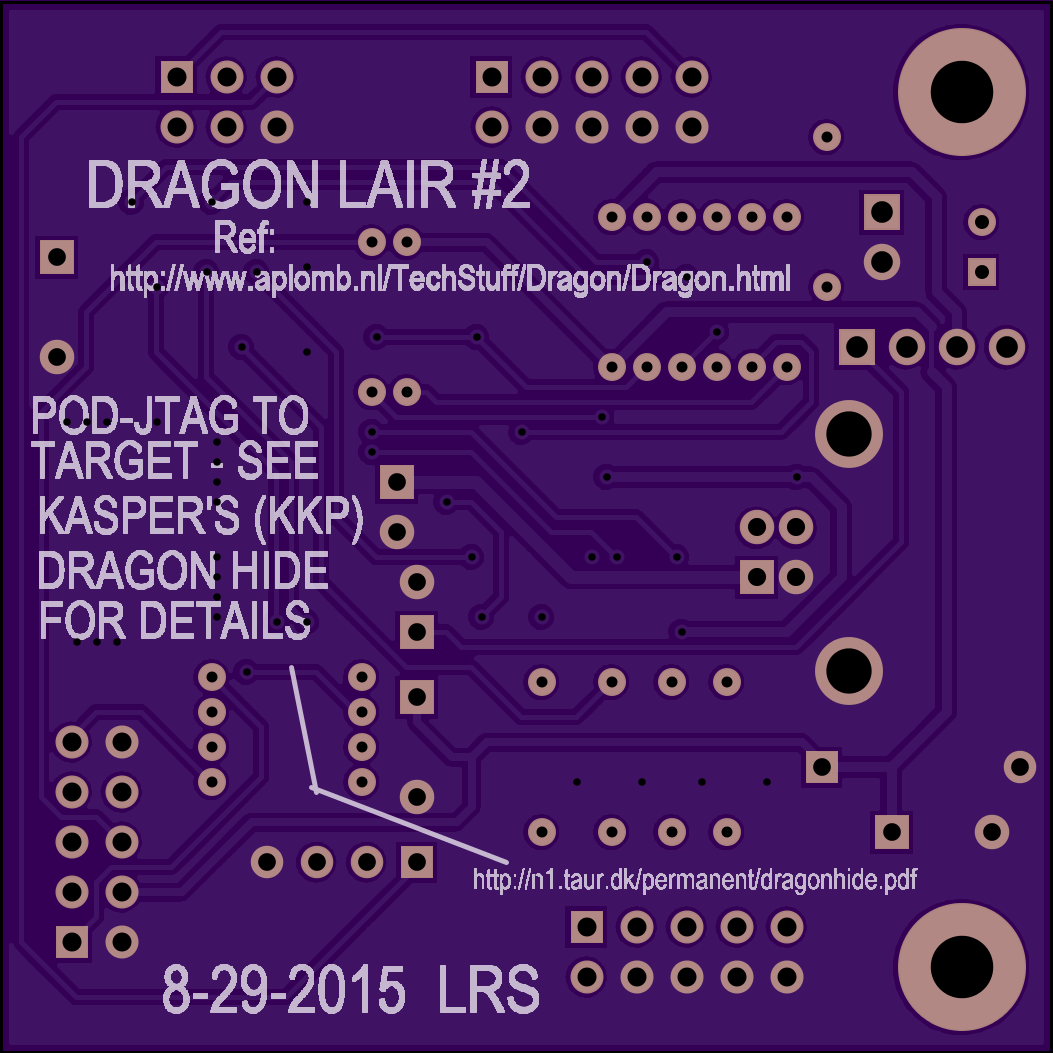
Dragon Lair #2
by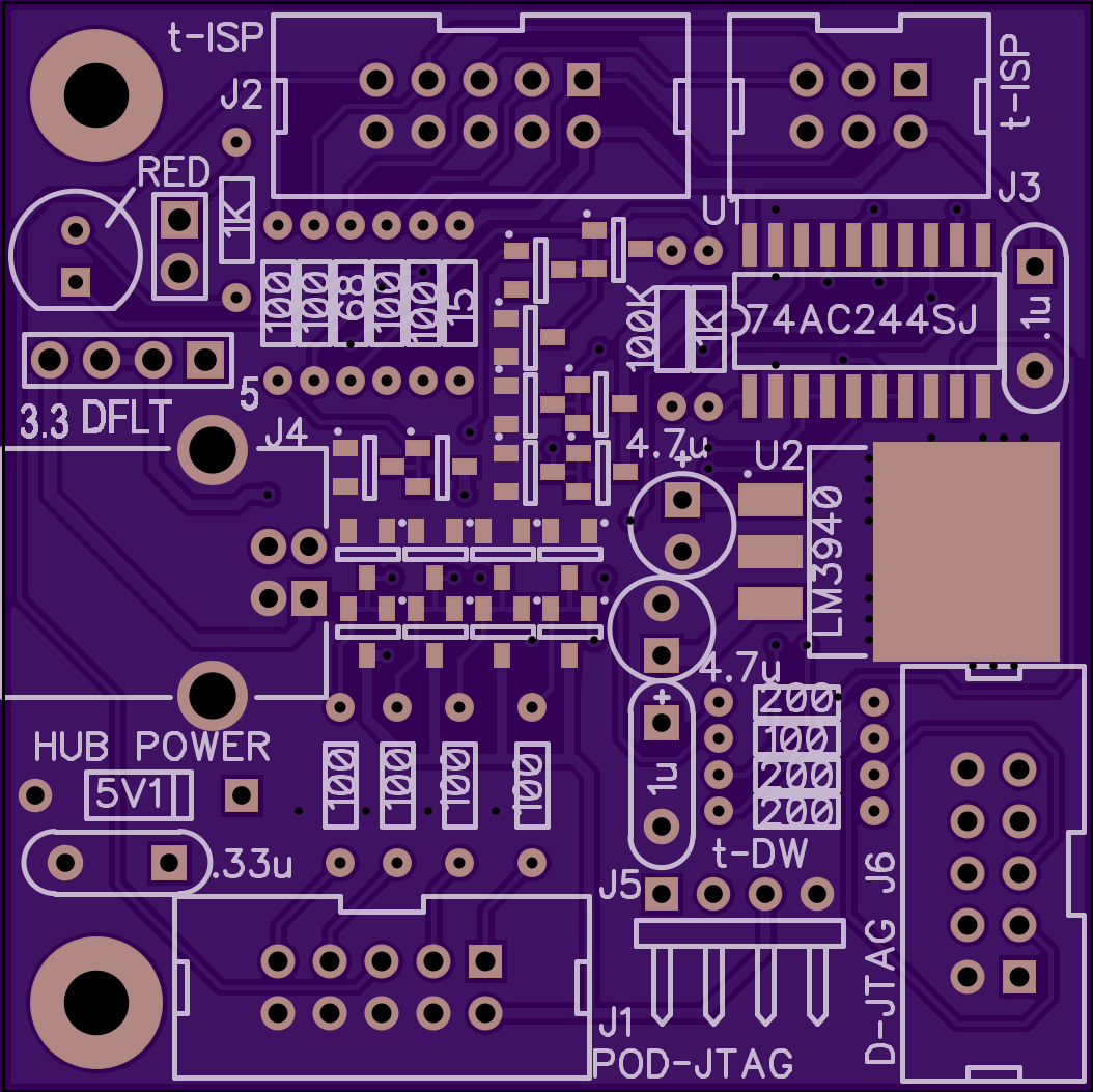
2
layer board of
2.11x2.11
inches
(53.49x53.49
mm).
Shared on
September 4th, 2015 22:20.
This is a rendition of the Dragon Lair board by Nard at: http://www.aplomb.nl/TechStuff/Dragon/Dragon.html
The POD-JTAG connector, J1, is not pinned out for standard JTAG pin sequence but is based on the improved signal integrity pin out as described by Kasper (KKP) in this document: http://n1.taur.dk/permanent/dragonhide.pdf
A small descrambler board at the end of the JTAG cable in the vicinity of the target IS REQUIRED to rearrange the signal sequencing for standard pin-out JTAG connectors. This descrambler is a very simple board and can be implemented with a small vector/vero board type circuit as a POD at the end of the ribbon cable. See Kasper’s .pdf document for information.
This is a protection/buffer board for the Atmel AVR Dragon programmer board that has some weaknesses due to cost constraints in Atmel’s design of the AVR Dragon. As in the designs by Kasper and Nard, there is no provision on this board for high voltage programming, which is possible on the Dragon. Be careful if you use the high voltage programming for resetting fuses and refer to the Atmel documentation. DO NOT USE this board for that application.
This is for the second version of the Dragon that has the mounting holes for mechanical purposes but it should be able to be used by the earlier version if mounting is done with some sort of sticky foam tape, etc.. This board piggy-backs over the Dragon and has a USB2.0 type B connector for power only oriented just above the USB2.0 type B of the Dragon. The Dragon needs to be powered by a powered USB HUB anyway, and this board optionally can be powered by another port of the same HUB if the target board is not to be self powered. Three selectable hub powered voltage regimes are allowed: +3.3V, +5V, and default target self-powered and these are pin strap selectable with the left 2 pins (+3.3V) or right 2 pins (+5V). The self powered default operation entails putting a 2 pin strap in the middle of 4 pins on the connector above the USB connector. The voltage of the target in any case is present for the Dragon to sense on its JTAG connector, J6 or D-JTAG to set the correct I/O level on the Dragon’s output structure. There is no provision to power the Target from the Dragon–this is a condition that is not recommended, so the USB HUB is there to do this function.
Please refer to Nard’s website and Kasper’s document for additional information on operation and usage.
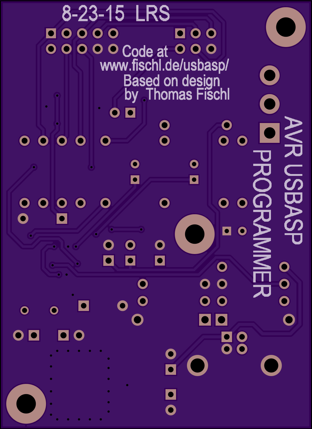
AVR USBASP_PROGRAMMER V1.0
by
2
layer board of
2.01x2.76
inches
(50.95x70.00
mm).
Shared on
August 24th, 2015 02:02.
A version of the classic Atmel ISP programmer by Thomas Fischl. This one supports 3.3V and 5V operation on the Programmer and Target and has Schottky ESD protection diodes on the 4 main lines for the ISP. Both 6 and 10 pin headers are supported. Mostly thru hole for easy assembly, the ATMega88 is a 32 pin TQFP and should be easy to solder for most people. The ESD diodes are simple SOT23 devices, BAT54C dual types and easy to solder as well. Fischl’s website is noted on the reverse side for all the firmware and operation guidance.
If I can find a way to submit a .pdf of the schematic it will go in here as well.