OSH Park
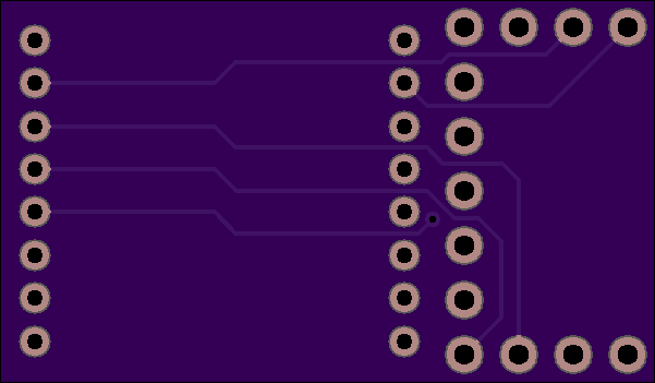
rfm69_adaptor2
- You need to sign in or sign up before continuing.
rfm69_adaptor2
by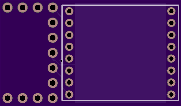
2
layer board of
1.20x0.70
inches
(30.53x17.86
mm).
Shared on
April 25th, 2014 21:09.
Connections:
    Teensy 3.x       RFM69
    ------------     ------
    pin 15 (CS)      NSS (Chip Select)
    pin 16           DIO0 (interrupt)
    pin 11 (DOUT)    MOSI
    pin 12 (DIN)     MISO
    pin 13 (SCK)     SCK
    3.3V             3.3V
    GND              GND
Detailed Tutorial: Adding A Low Cost Wireless Packet Radio To A Teensy 3 Microprocessor (PDF)
When using the RadioHead library, edit the Arduino sketch examples to specify pins 15 and 16. For example:
    // Singleton instance of the radio driver
    RH_RF69 rf69(15, 16);
Discussion and more documentation for this adaptor can be found here:
http://forum.pjrc.com/threads/25897-Adapter-board-RFM69W-radio-for-Teensy-3-Also-diagnostic-software
A newer version of this PCB was designed, with the ability to disable the SPI SCK signal (possibly causing RF interference on the RFM69 module), but so far it is untested.