OSH Park
ESP8266-01 RemoteButton
- You need to sign in or sign up before continuing.
ESP8266-01 RemoteButton
by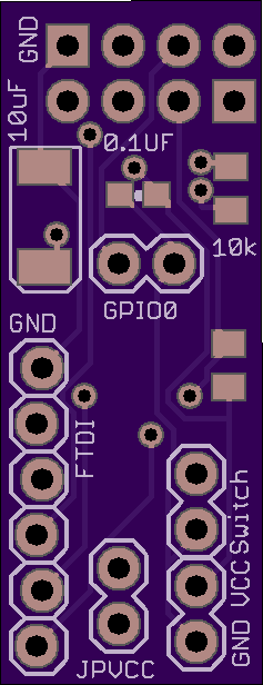
2
layer board of
0.47x1.23
inches
(11.99x31.24
mm).
Shared on
July 5th, 2016 02:34.
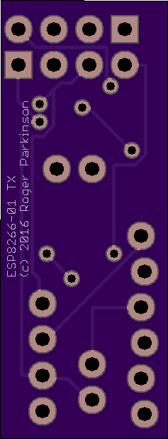
The board holds through hole connections for an ESP8266-01 and breakouts for an FDTI, VCC and GND. It is small enough to solder the ESP to and still leaves the ability to plug in an FDTI to reflash. There’s a jumper for GPIO0 and it uses the DTR from the FDTI to pull RST low. You can power the ESP from the FDTI by putting a jumper on JPVCC but the FDTI won’t provide enough power to actually run the ESP after flashing. The ‘Switch’ breakout uses CH_PD. Connect an n/o switch to this and the ESP can detect it. More detail at https://github.com/RogerParkinson/ESP8266-automation