OSH Park
Shared projects
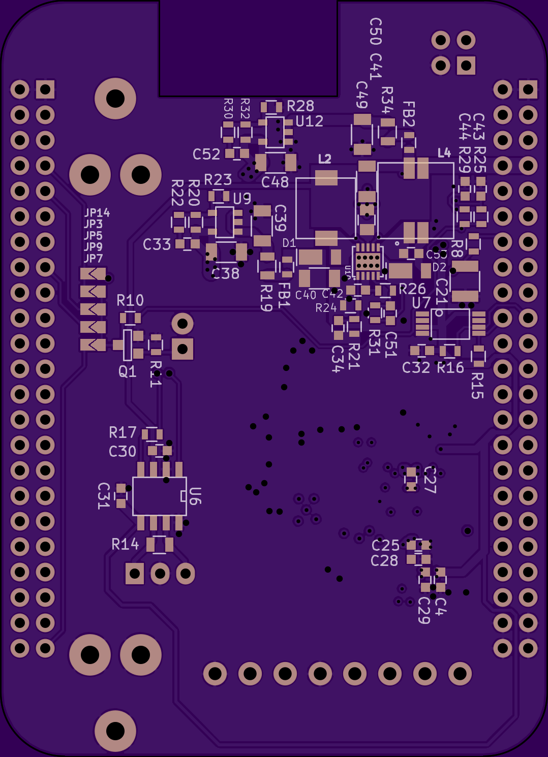
SeisCape
by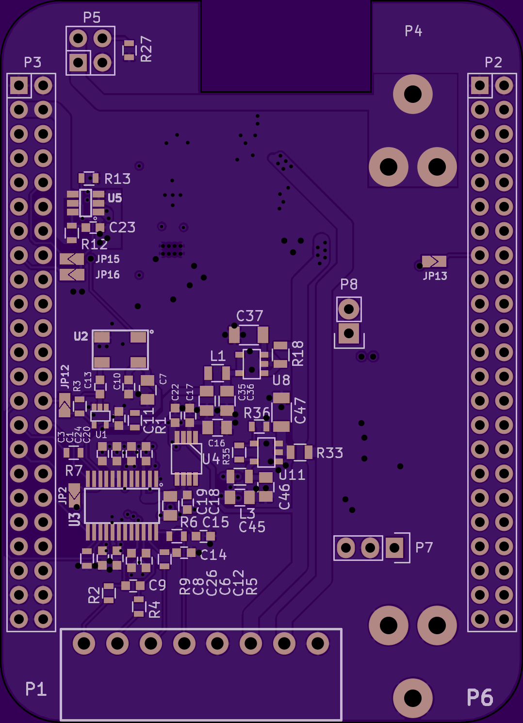
4
layer board of
2.16x2.98
inches
(54.76x75.72
mm).
Shared on
September 3rd, 2015 15:49.
Beaglebone Black cape with 24-bit ADC and power supplies for Nelson/Nordgren FBV seismometer
Openvision
by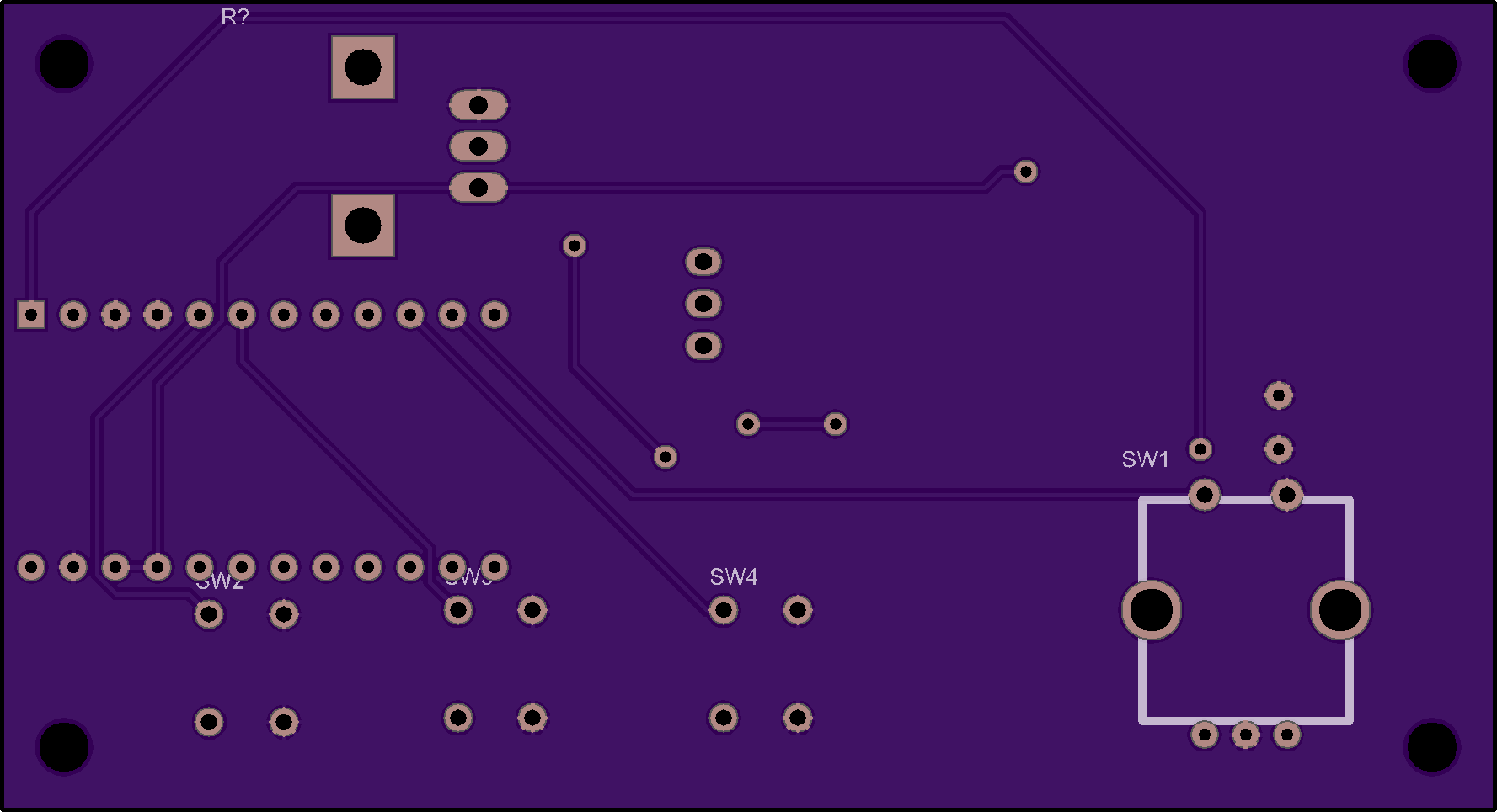
2
layer board of
3.55x1.93
inches
(90.27x49.02
mm).
Shared on
September 3rd, 2015 13:53.
Pull-Up v1.01
by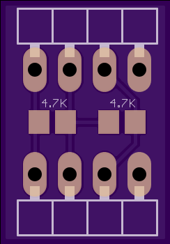
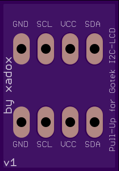
2
layer board of
0.49x0.70
inches
(12.40x17.78
mm).
Shared on
September 3rd, 2015 12:04.
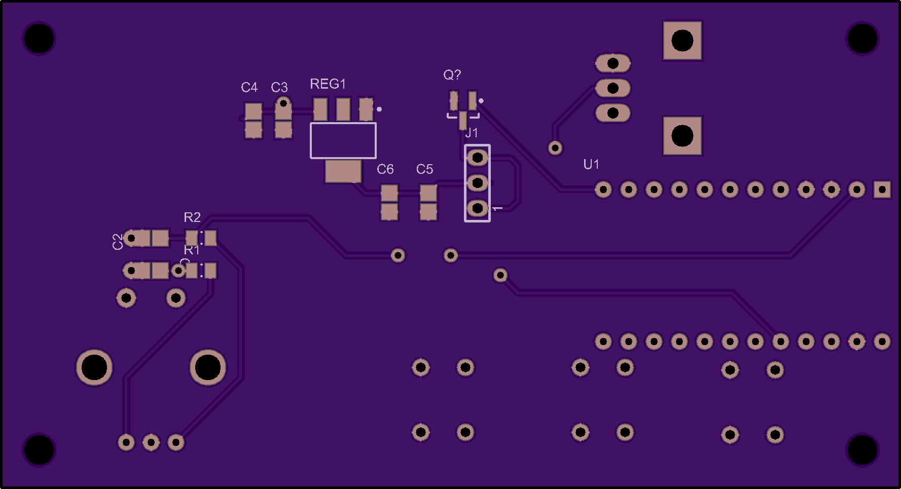
Low Power Node PTH v1 Connection Board v1
by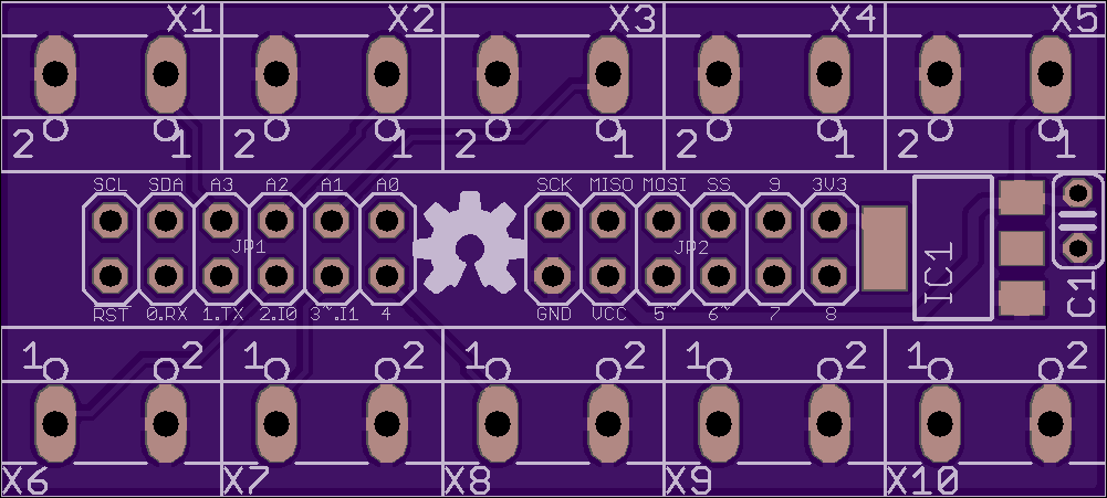
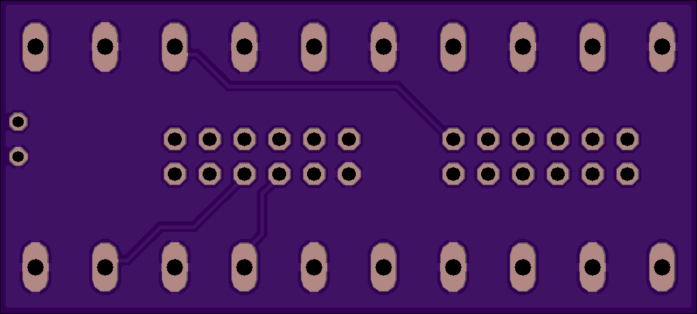
2
layer board of
2.00x0.90
inches
(50.83x22.89
mm).
Shared on
September 3rd, 2015 07:28.
Companion board to Low Power Node PTH v1-1, to allow easy connection of a number of pins and provide 3V3 regulated from VCC (for use by the NRF24L01+ or other parts).
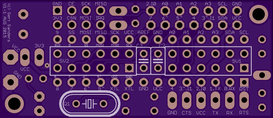
Low Power Node PTH v1-1 (atmega328p and NRF24L01+)
by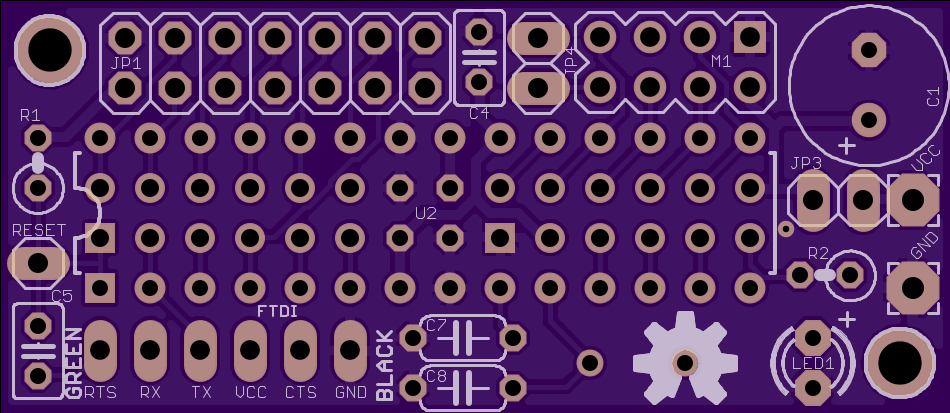
2
layer board of
1.90x0.83
inches
(48.29x20.98
mm).
Shared on
September 3rd, 2015 07:25.
Low Power Node based on ATMEGA328P and NRF24L01+, all through-hole components. It can use a companion connection board (in which it plugs directly): Low Power Node PTH v1 Connection Board v1.
You can also add another board on the topside next to the radio (second header is provided: JP1).
There is a jumper (JP3) to choose connection of 3V3 and 5V nets (in case one uses a battery). If 5V is applied to the VCC terminal, and you want to use the NRF24L01+, then connection to the companion board is needed. This second board houses a 3v3 LDO regulator.
A second jumper (JP4) is provided to connect the IRQ output of the NRF24L01+ to pin 2 (INT0) of the processor.
A pin connected to RESET is available so you can add an external reset switch. All usefull pins are broken out, I use female headers on these points.
The board has a FTDI port for uploading sketches, and I use a version of Optiboot 4.4 which flashes the led connected to pin 14 (Arduino pin D8 instead of the traditional D13).
The crystal can be mounted on top or bottom side. If you use the companion board with screwterminals like I do, then you need to put the crystal on top-side. For shielding from the nRF24L01+ it would be better on the bottom side. I’m using both setups.
Images below are the first board spin, v1-1 adds an extra decoupling capacitor next to the interrupt-jumper.


