OSH Park
Shared projects
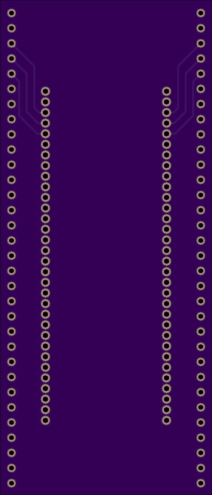
SDIP64 to DIP64 ZIF Adapter
by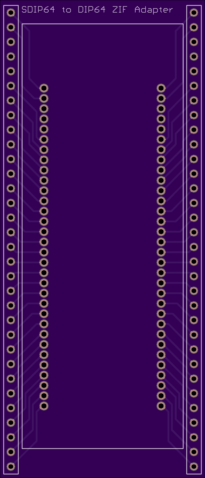
2
layer board of
1.40x3.26
inches
(35.56x82.88
mm).
Shared on
July 24th, 2015 18:08.
SDIP64 to DIP64 ZIF Adapter
SDIP64 - 0.070" pitch x 0.9" width (swipe socket or 3m textool) DIP64 - 0.100" pitch x 1.25" width
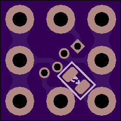
APA106 Breakout V2
by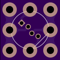
2
layer board of
0.50x0.50
inches
(12.73x12.73
mm).
Shared on
July 24th, 2015 17:14.
Second version of a board I will be using to construct large grids of arbitrary shape/size out of APA106 RGB LEDs. The first version used a diamond orientation, and the new version uses a more normal square orientation- now all wire connections in a grid will be the same length. The leads for the APA106 were also separated slightly to make for easier manufactuering.
TinyBuck
by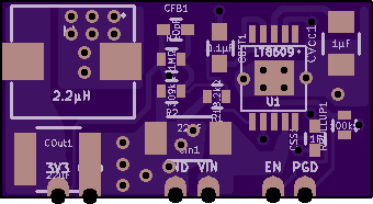
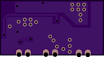
2
layer board of
0.68x0.36
inches
(17.32x9.22
mm).
Shared on
July 24th, 2015 15:19.
wut
MySensor 3.3V Pro Mini or 5V Pro Mini with NRF24L01+ V2.0
by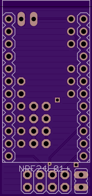
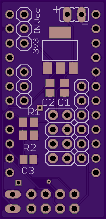
2
layer board of
0.74x1.52
inches
(18.72x38.61
mm).
Shared on
July 24th, 2015 13:08.
PCB will take 3.3V pro mini or 5V pro mini and connects to NRF24L01+ radio.
Version 2 Fixes
- fixes some orphaned Ground Planes
- Replaces the thru-hole resistors with SMD
- adds power “ports” for various things like relay, PIR, and Temp sensors
For 3.3V Battery powered Sensor:
- No place the AMS1117 regulator
- Tie 3v3,IN,and VCC together.
- Can also place Resistors R1 (1M) and R2 (470k), and C3 (0.01uF) to measure battery voltage on A0
- Should also place C2 (10uF to 47uF or whatever works best in your environment) for more stability on Radio.
For 5V powered sensor (like from USB charger):
- Place AMS1117 3.3V regulator.
- Place C1 and C2
- Tie VCC to VIN option.
- Do NOT place R1, R2, or C3 (no battery sensor).
Other Notes
- D8 – D3 have extra headers
- A3 – A1 have extra headers
- A7 – A4 have headers on pro mini itself.
- See mySensors.org for more information. This PCB is not officially affiliated with MySensors.
OpenTPM
by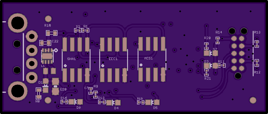
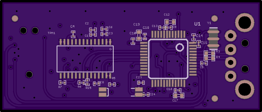
4
layer board of
1.79x0.76
inches
(45.42x19.41
mm).
Shared on
July 24th, 2015 11:59.
OSHW Trusted Platform Module