OSH Park
Shared projects
Baby Fartduino Rev B.1
by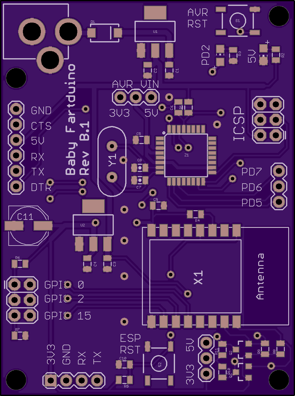
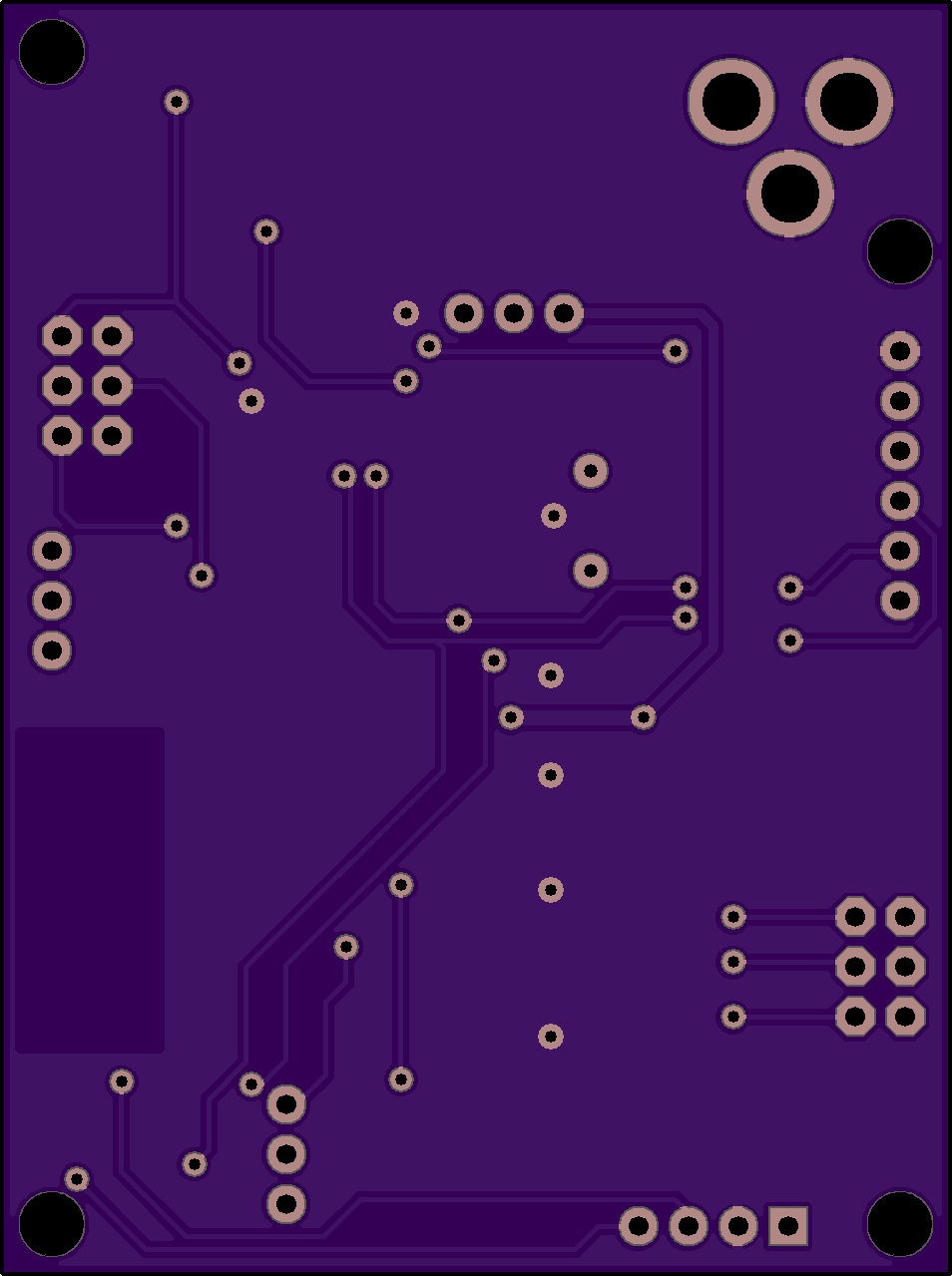
2
layer board of
1.91x2.56
inches
(48.49x65.00
mm).
Shared on
June 30th, 2015 20:17.
SMT style, boyeeeee!
8-Port Optoisolator
by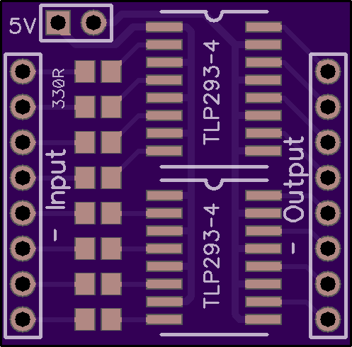
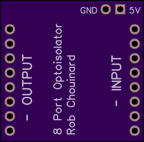
2
layer board of
0.99x0.98
inches
(25.25x24.92
mm).
Shared on
June 30th, 2015 18:46.
8-Port Optoisolator for TLP293-4 5V
Pixhawk 5v trigger cable
by
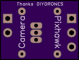
2
layer board of
0.56x0.42
inches
(14.12x10.69
mm).
Shared on
June 30th, 2015 17:33.
enables relay output for 5v devices on aux 5/6 on the pixhawk. Circuit by Reuben on DIYDRONES. 2 220k resistors and a bc 547 transistor (or equivalent, its just a dang relay for the power line). requires 5v being fed to the servo rail.
Centv3
by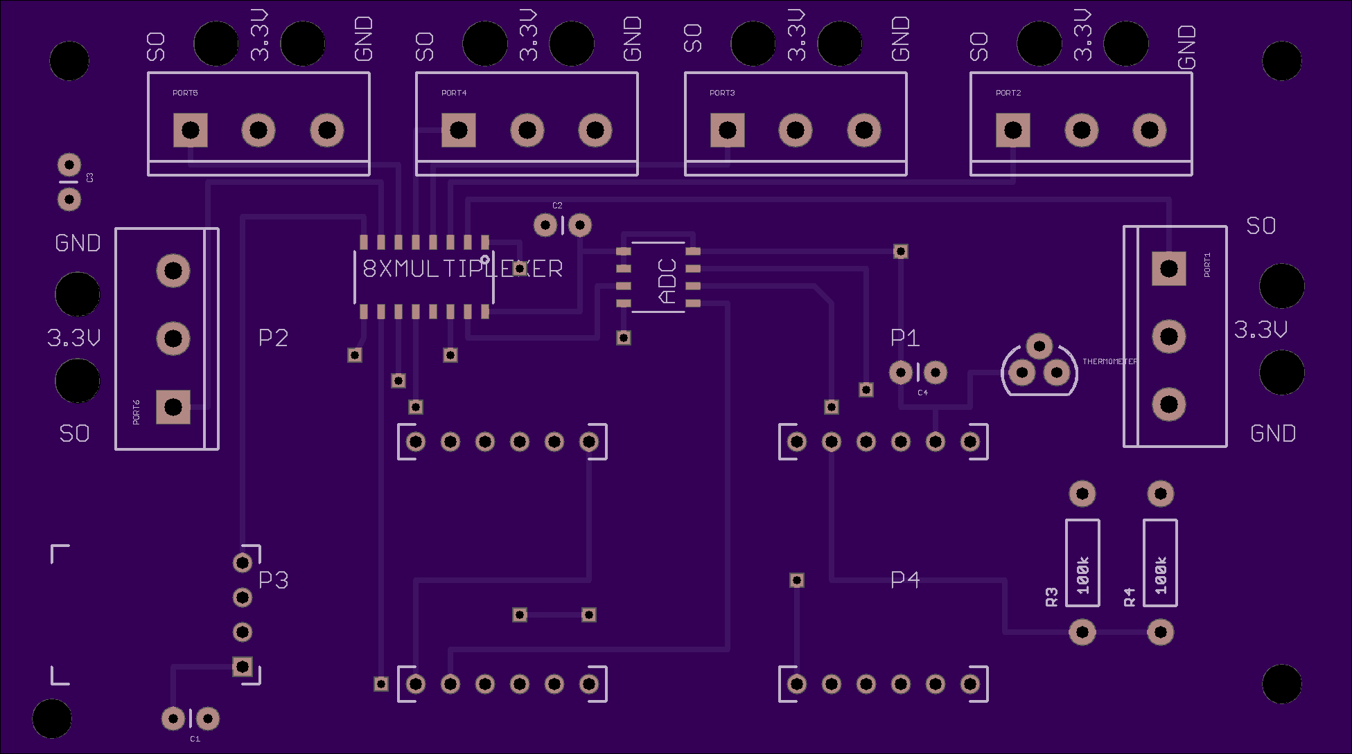
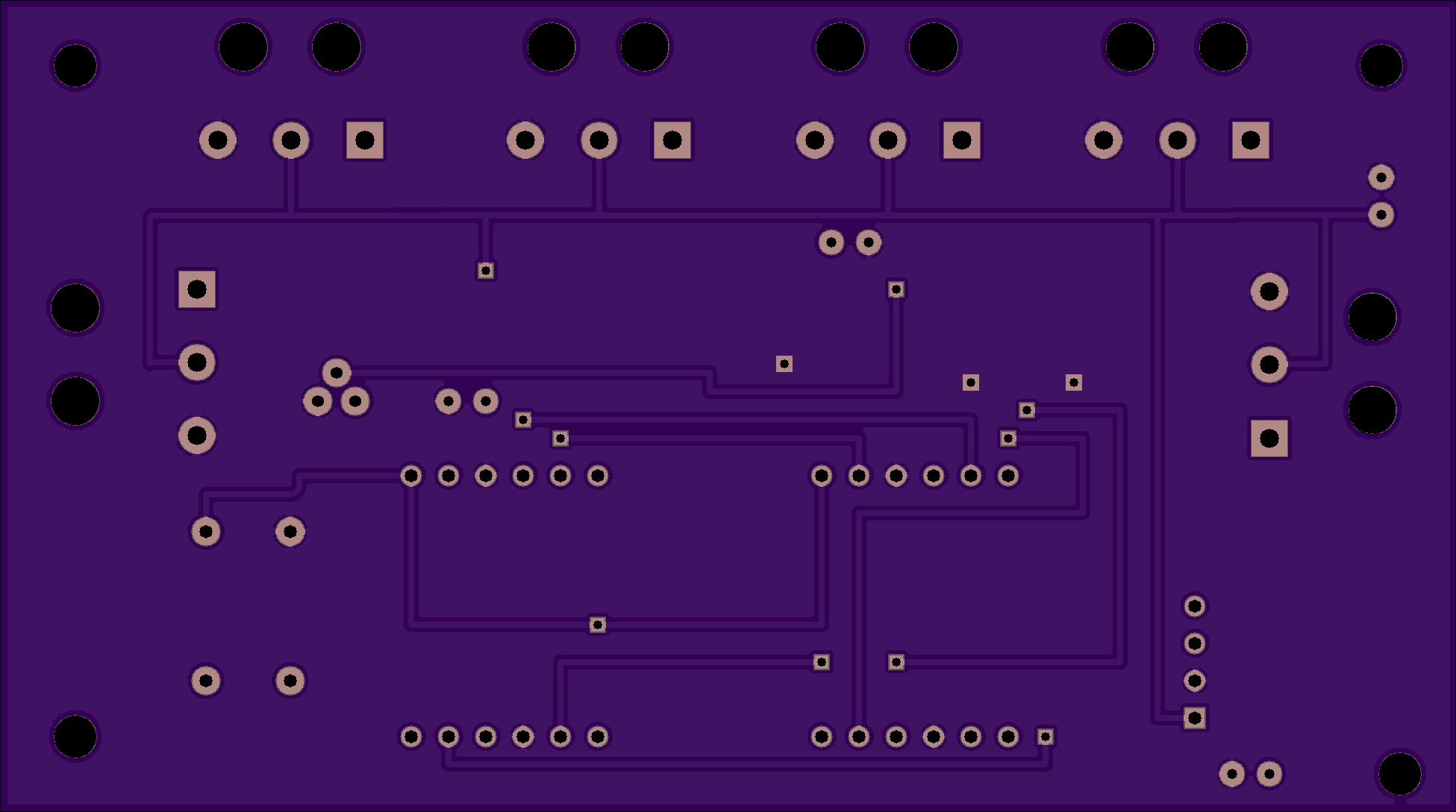
2
layer board of
3.90x2.18
inches
(99.09x55.27
mm).
Shared on
June 30th, 2015 17:19.
New cent pcb
Intel Server Front Panel Board
by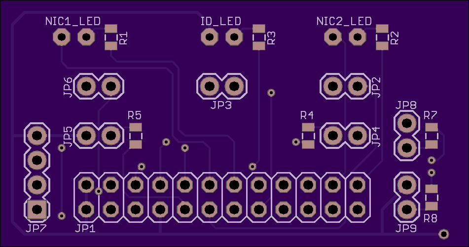
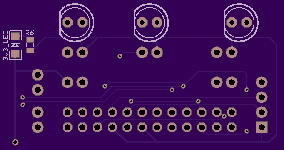
2
layer board of
1.90x1.00
inches
(48.29x25.43
mm).
Shared on
June 30th, 2015 16:49.
Intel Server Front Panel
Board for Intel Server Front Panel 24 Pin Header.
It has been developed to be able to use a standard chassis with an Intel server motherboard. Simply connect the ribbon cable to the motherboard and chassis’s cables to the Panel board.
Features:
- 5V STB LED (Included on PCB)
- Power LED (External Connector)
- HDD Activity LED (External Connector)
- ID LED (Included on PCB)
- NIC 1 Activity LED (Included on PCB)
- NIC 2 Activity LED (Included on PCB)
- System Status LED#1 (External Connector)
- System Status LED#2 (External Connector)
- Power Button (External Connector)
- Reset Button (External Connector)
- ID button (External Connector)
- SM Bus Header to read data (External Connector)
24Pin Header Pinout

Todo’s
- 1-Wire Temp Sensor
Form more info see: Intel Header
This is a test project, was made only in order to use the feature without using an Intel chassis.