OSH Park
Shared projects
MinimOSD_MK2
by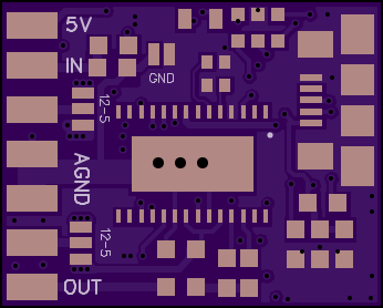
4
layer board of
0.87x0.70
inches
(22.00x17.68
mm).
Shared on
May 26th, 2015 15:54.
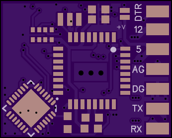
MinimOSD_MK2
Luc.id2
by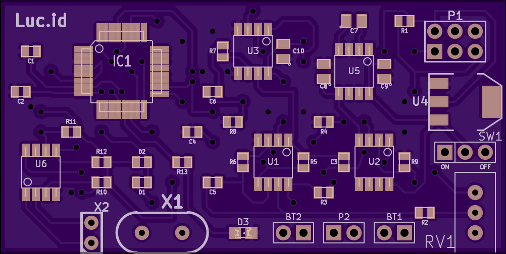
2
layer board of
2.51x1.26
inches
(63.65x31.90
mm).
Shared on
May 26th, 2015 14:33.
Lucid dreaming device check out https://hackaday.io/project/3715-lucid-dreaming-device-tacs for more info!
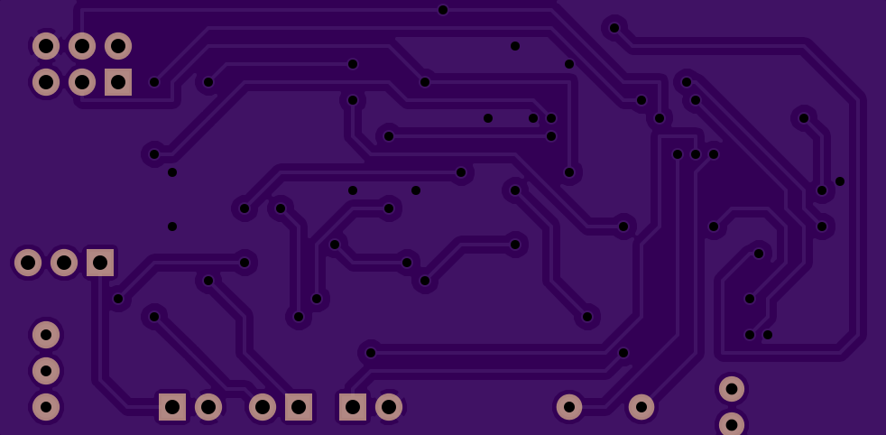
EAS Mindreader quad pot
by
2
layer board of
0.86x0.65
inches
(21.82x16.46
mm).
Shared on
May 26th, 2015 13:59.
https://www.muffwiggler.com/forum/viewtopic.php?t=76398
RLD LED String
by
2
layer board of
1.80x1.90
inches
(45.72x48.29
mm).
Shared on
May 26th, 2015 06:49.
LED Bias Board for SY’s Red Light District
ESP8266 ESP-01 & ESP-03 Programmer v1.5
by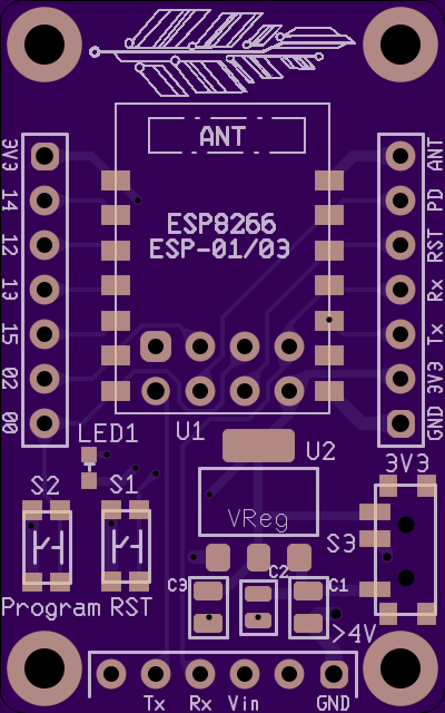
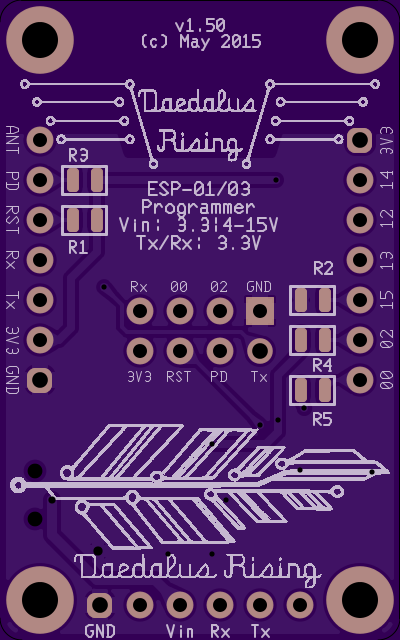
2
layer board of
1.00x1.60
inches
(25.43x40.67
mm).
Shared on
May 26th, 2015 03:28.
ESP-01 & ESP-03 Breadboard Breakout
Provides voltage regulation and switches to enter programming mode (over FTDI or serial UART).
Goal
Provide a simple-to-use programmer for ESP8266 modules similar to Adafruit Huzzah ESP8266 module.
Changes in v1.5 include: No ground plane under antenna, mounting holes, clearer layout, labeled header for ESP-01, resized board to accommodate entire length of ESP-01.
Usage:
Solder all components on, including your choice of ESP-01 or ESP-03. Insert UART connection into header at end of board. S1 will reset the board. To program board, hold S2 while hitting S1. S3 will select between 3.3V and 5V input on Vin (towards the ESP module is 5V).
Schematic
Schematic, BOM, and Ultiboard layout files can be found at the github repo.
Components:
U1 can take either castellated SMD pads (ESP-03) or a 2x4 .1" pitch female header (ESP-01).
R1-R4 = 10k 0603, R5 = 1k 0603.
C1&C3 = 10uF 0805, C2 = 0.1uF 0603.
LED1 = LTST-C190KFKT Orange 0603 LED.
U2 = LD1117AS33 3.3V 1A Voltage Regulator.
S1-S2 = KMR221NG LFS pushbutton momentary SPST switch. S3 = PCM12SM SPDT slide switch.
Mounting holes provided are for #2 US screws (0.090" diameter). The spacing is 1.4" vertical, and .8" horizontal.
The breakout headers are spaced at 0.8"