OSH Park
Shared projects
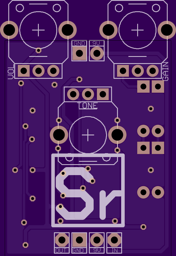
Quantum Effects Strontium Screamer v1.1
by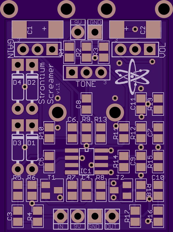
2
layer board of
1.12x1.46
inches
(28.52x37.01
mm).
Shared on
February 21st, 2016 18:32.
Modded SMD Tube Screamer
build doc:
http://felix.kalium.org/upload/share/builddocs/Strontium_Screamer_build_doc.pdf
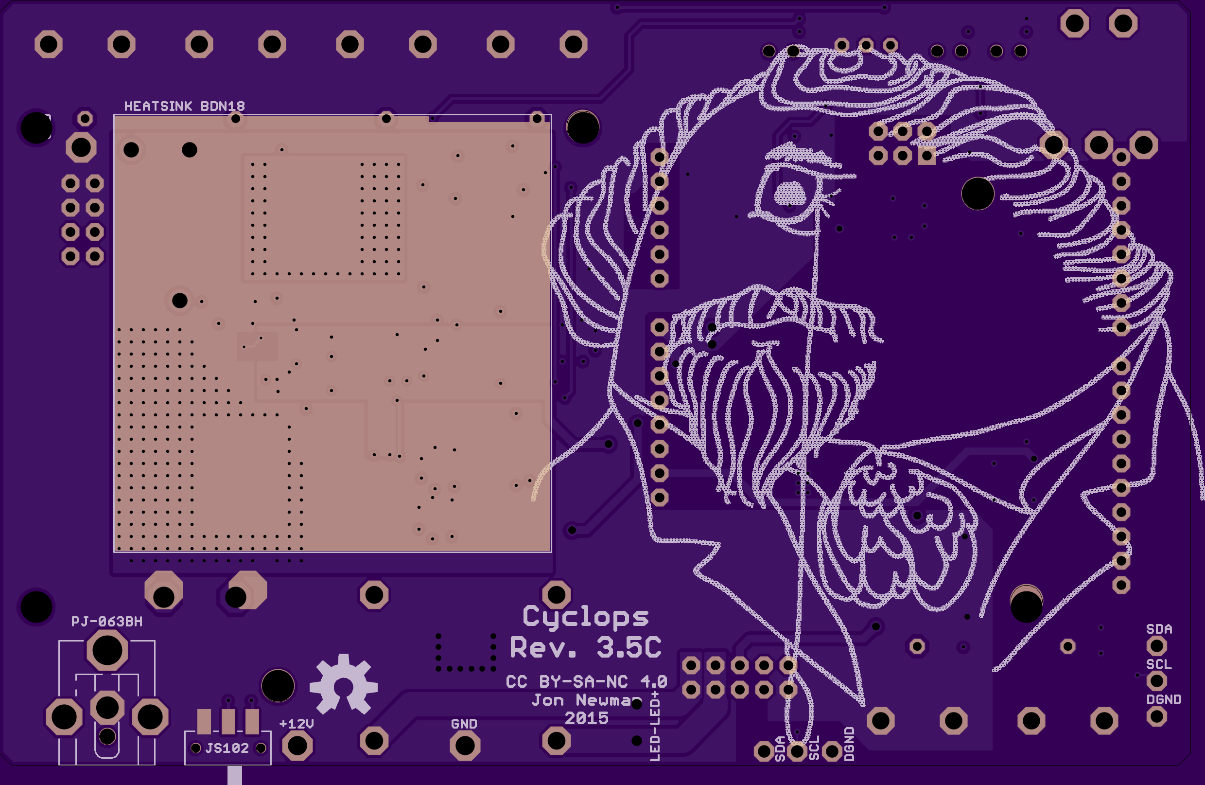
Cyclops Rev. 3.5D
by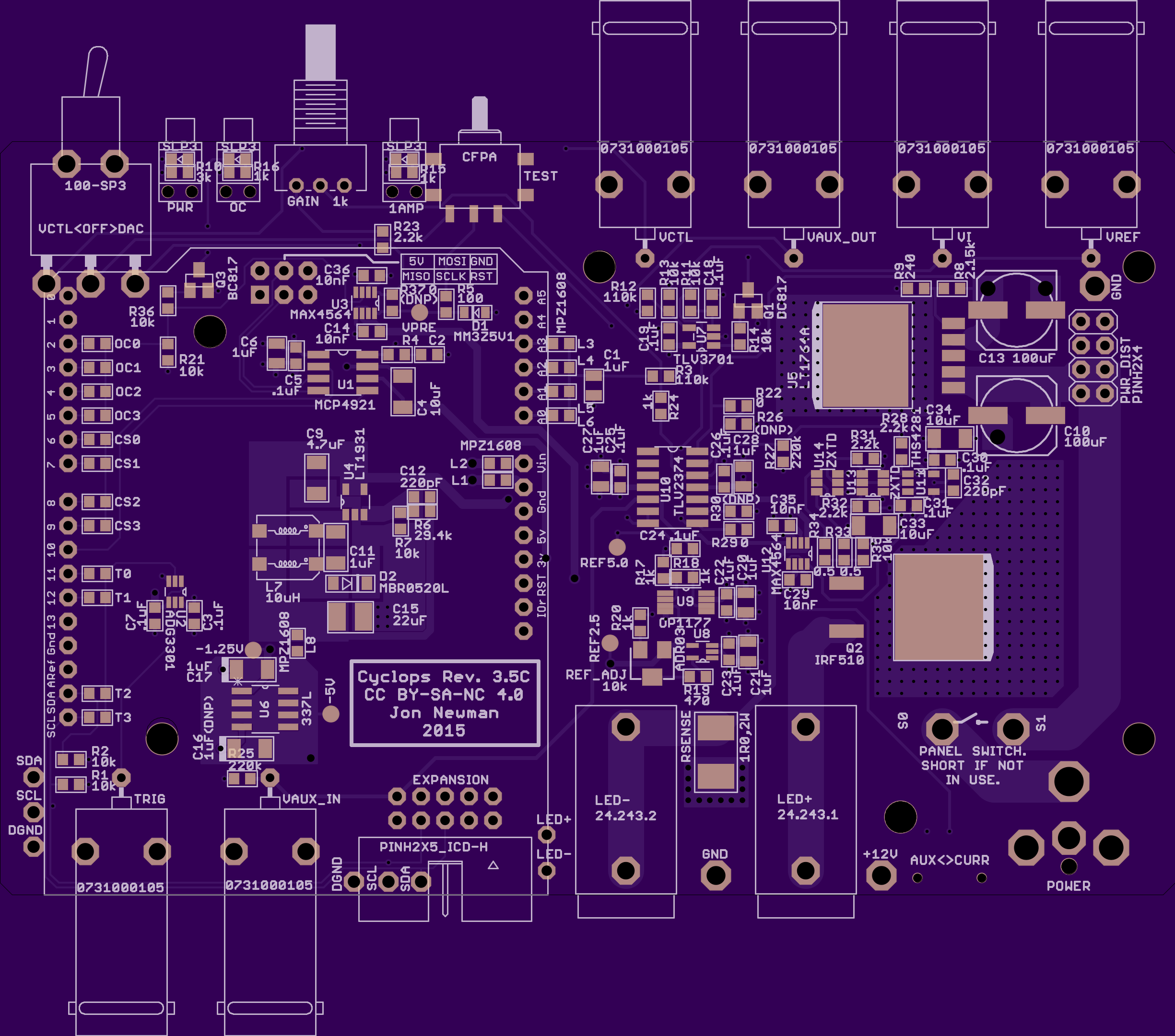
4
layer board of
4.90x3.15
inches
(124.49x79.88
mm).
Shared on
February 21st, 2016 18:25.
Wide Bandwidth LED Driver
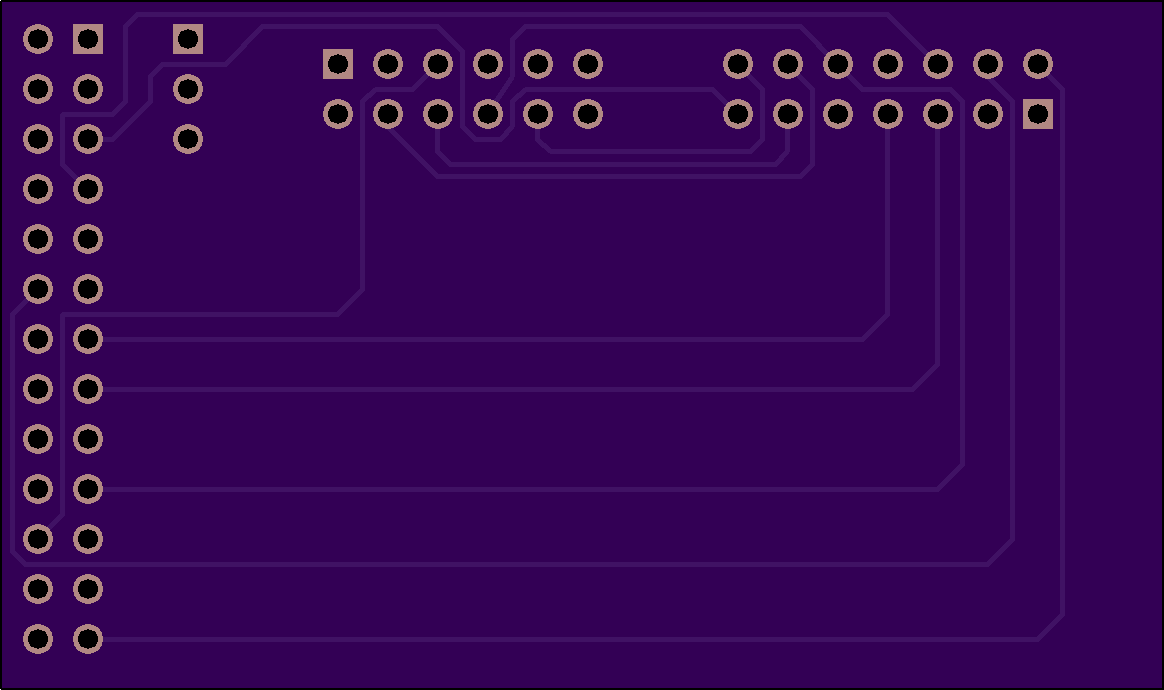
rpi-6lowpan-adapter
by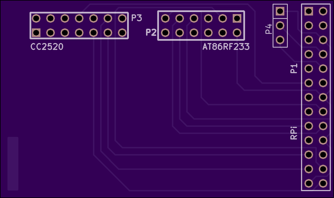
2
layer board of
2.33x1.38
inches
(59.16x35.03
mm).
Shared on
February 21st, 2016 12:05.
Adapter PCB to use AT86RF233 and TI CC2520 on the RPi (v1 and v2) at the same time.
NEDONAND-2
by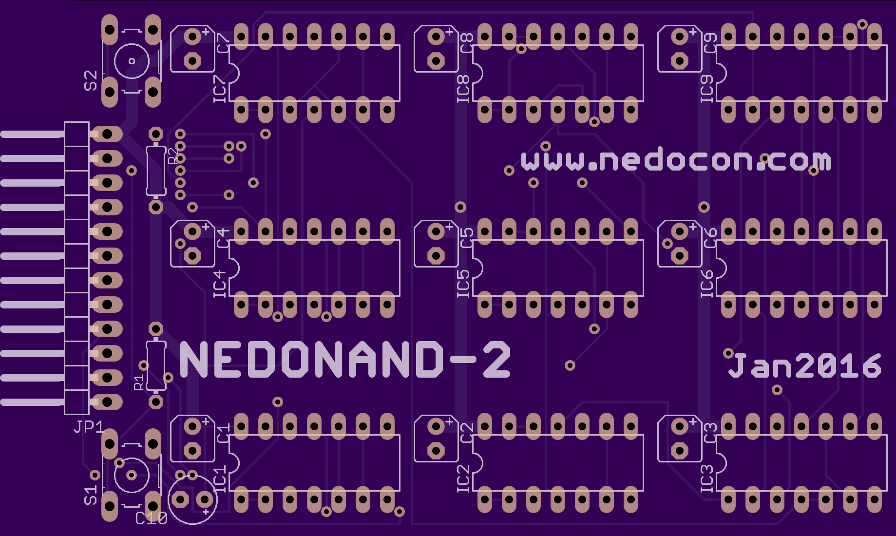
2
layer board of
3.39x2.20
inches
(86.06x55.88
mm).
Shared on
February 21st, 2016 04:25.
2nd board for NEDONAND project
It’s dual edge triggered D-flipflop with separate reset inputs. Pins description (from right to left):
1) GND - ground;
2) D1 - first data input;
3) ^C1 - first clock input (front active);
4) /R1 - first reset input;
5) Q1 - first straight output;
6) /Q1 - first inverted output;
7) D2 - second data input;
8) ^C2 - second clock input (front active);
9) /R2 - second reset input;
10) Q2 - second straight output;
11) /Q2 - second inverted output;
12) VCC - power +5V.
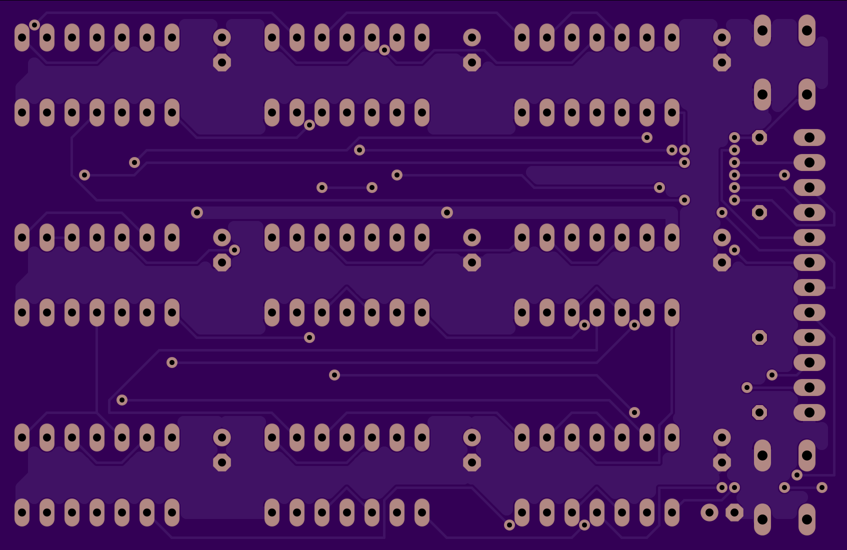
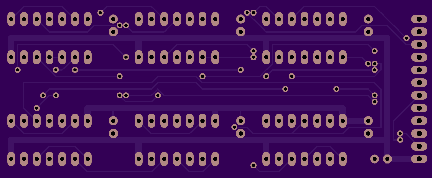
NEDONAND-1
by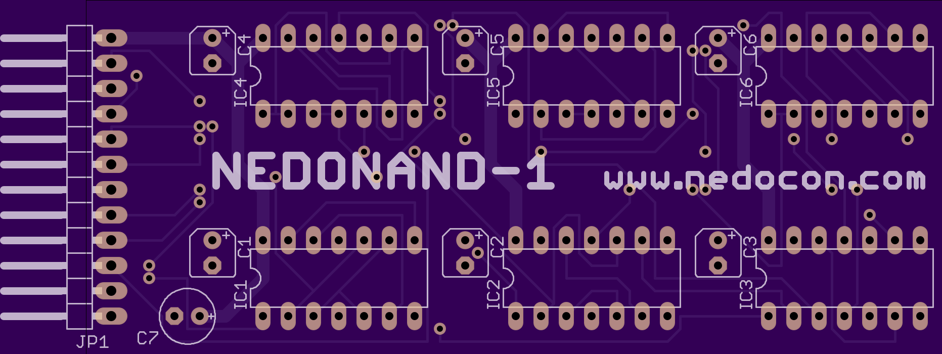
2
layer board of
3.39x1.40
inches
(86.06x35.56
mm).
Shared on
February 21st, 2016 04:25.
1st board for NEDONAND project
This is a 1-bit slice of NEDONAND ALU supporting shift right RRC (000), shift left RLC (001), NAND (010), XOR (011) and ADD (1xx) operations. Pins description:
1) GND - ground;
2) O0 - bit 0 of ALU operation;
3) O1 - bit 1 of ALU operation;
4) O2 - bit 2 of ALU operation (if it's "1" then O0 and O1 are ignored);
5) A - input bit A (always from accumulator);
6) B - input bit B (might be from register or number);
7) C - input bit C (carry);
8) H - higher bit for rotation right;
9) L - lower bit for rotation left;
10) COUT - carry out;
11) DOUT - data out;
12) VCC - power +5V.