You are not logged in.
- Topics: Active | Unanswered
Pages: 1
#1 Re: Feature Requests » Calibration plate estimated printing time » 2017-11-13 22:21:34
I also support idea to finalize this feature, and make them more user fiendly. Time for this feature is one of the thing that need to be defined. I'm sugesting one more thing. Elements that is printed, we need to clean before serius examination from residu or resin. If it is not a big problem I will ask that desirable timing for certain square will be imbost in the midle. During cleaning in ultrasonic clener, that I use all the time, for cleaning parts after print, parts fall of the printing platform, and I'm in position to guess, what square is exposed with what timing. This will help a lot. Recently I have got new quantity of resin from reliable producer, and exposition time is 2 timesl longer than previus one. So this function is necesary to use often to be sure that we will achive proper print. Thank's for listening.
#2 Re: Everything else » Disabling hallowing and hatching on Raspberry Pi » 2017-11-04 22:38:52
Hi, For jewelers it is most important to have holowing part printed. This alowed to have minimal expansion during bunout cycles, and minimal ashes residue during same proces, and when part riches temperature that create fire in plaster, this fire actualy destroy plaster surface, and with minimal content of materila, this fire-burning, make les distruction, wich is mostly comon in lostwax technology. So yes we can use software to create hollow model and then send to slicer in NanoDLP, or to do this in other different software, but to have this function availabile for other user that can not aford Netfabb or Materialise magics, I will vote to stay and if in time you may develop coowork with windows version on regular PC. Thank's for listening .
#3 Feature Requests » Barrel distortion » 2017-09-12 13:09:26
- Sacha
- Replies: 1
Hi Shahin, Barrel distortion is covering projector that project directly thru center of lens. Usually all projectors are made to project on certain angle, so frame is usually i position that lower side of frame is passing thru X axes and projecting image is straight line. Here we dont have any problem, but upper side of the frame is under huge distortion. Y sides usually can be adjusted by projector function. As I understood, your Barrel distortion function are equally make adjustment to both X sides, bottom and upper, and also two Y sides. Can you do something about that. I know that inside of projector is small square lens that can adjust projecting angle, but is limited to certain angle, and newer can project directly to center of lens, so I believe some more function to adjust that will make us possibility to reach perfect square frame. I hope that you understand what is my problem and that you can help us to solve this issue. Best regards Raca Sasa
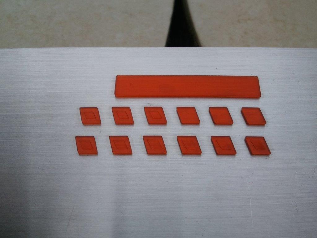
#4 Tips, Tricks and Tutorials » Recommended polymerisation time » 2017-07-25 12:51:25
- Sacha
- Replies: 1
Hi to all. I have try Calibration plate program under NanoDLP for new resine that I have found. First of all Program only calculate normal layer exposition thru his definition. Burnin layer are not defined. I believe that we need this option as first option on this program to be defined. I would like to know how much is recommended, how much is undercured or how much is owercured. If you can just provide us photo of the samples will be fine to determine what we need to achieve for proper polymerization. Then we come to second thing and this is Normal cure exposition. On photo you can see exposition in 0.1 , 0.2 , 0.3 , 0.4 , 0.5 , 0.6 , 0.7 , 0.8 , 0.9 , 1.0 , 1.3 , 1.5 sec. Which will be considered as proper exposition? i believe that this is fundamental thing and if we skip this a lot of problems later will be hard to understand. This is elementar thing that need to be defined in any type of photocuring printer ! On photo you can see that after 0.5 sec surface become slightly mat until 0.4 and 0.5 sec are glossy. Sharps edges become precisely defined from 0.6 sec. Other thing that I like to ask , is dare any possibility that time that is defined can be printed on samples, so that after cleaning we can know which one is which ? I hope that this will help all of us and defined parts in future Manual that we wait for long time. Best regards Raca Sasa
#5 Everything else » ASUS Tinkerboard » 2017-03-29 13:03:11
- Sacha
- Replies: 2
Hi Shahin,
There is recently a new development board, the ASUS Tinkerboard, which runs Debian (but not Raspbian) and is comparable to the Raspberry Pi. Is NanoDLP compatabile with the Tinkerboard? (I would like to confirm that before I decide to purchase it).
Regards,
Sasa Raca
#6 Re: Bug Reports » Working problem » 2017-03-24 18:06:21
Hi Shahin, Your suggestion resolve problem. Even I have fix resolution problem By putting 38 Percentage on Override X/Y Resolution under profile and also on Setup under XY resolution in Microns. Now I have projected proper size of image, but still did not project on the start. I needed to stop printing, wait until finish the command and then again start from beginning. Then in second turn start projecting image. Can you do something about that ?
#7 Re: Bug Reports » Working problem » 2017-03-23 16:11:13
Hi thanks' for answer but I need more explanation. Where to look and what to do, Exactly! And what about some times image shows and some time don't. This is different issue? Thanks' in advance ! BR Sacha
#8 Re: Bug Reports » Working problem » 2017-03-22 18:26:27
It does not project first layer, and then I have wait for second and same thing happen, no projection. I have press Stop, machine went up some 20mm and came down until crush to VAT platform. It has continue pushing some time and then stops, because driver did not allow any more work. I have turn off machine , then turn on again and same thing happens again, and again. I have update few times after Clean instal of Raspbian and Initial NanoDLP and same happens again. I always measure Z axes before print. About Delay I have never hear anything about that, dont know where to look. Thanks' for video I will try to see it later. This is right way to show how to deal with software. Thanks' for the help. BR Sacha
#9 Bug Reports » Working problem » 2017-03-22 14:59:57
- Sacha
- Replies: 8
HI To All, I was patient, but for my previous posts nobody responded or it seems that I have only this issue. I'm experiencing now serious problem, and I don't know where to look to fix it. Software was upgraded from 1330 to 1370, and after to 1373, with idea that new update will fix my problem, but same things appear again and again. I will give you my procedure of printing, in reason to be correct if I do something wrong. I dont claim to be so smart and know everything, especially since nobody jet has provide detail manual for this program, nider written form or video, except mUVe printer manual from with 1091 version of software old one year.
First I turn machine on, and Z axes after certain period of time start go up until reach Home limit, passe by for several millimeters and come back to home limit position.
At the same time when I start printer ON, I start DLP projector as well. ( warm up period ). First after I do after setting up Z axes, I go to Projector calibration, and send signal on FullHD Red Calib. When this appear I close shutter and go to Boundaries. Since I have several option for pixel size , I need to measure Square and adjust to certain dimension. When I achieve desired dimension and sharpness of printing eria , I go to Z axes calibration. I move Z axes until I reach desired level and then I start Red button Mesure Z axes. Machine goes up to the Home limit and I can proceed to printing. Since part is printed few times I will not explain how to upload file and slice them or upload already made PNG file sliced on external software, but file is ready for print , and shows first layer on preview. It appear number of layers. and starting layer. So I press Start from begining and with Z axes to go to printing position.
Now problem appear. DLP projector don't send first layer light , even it is shoved on prevue. Then I need to stop printing and wait until system finish moves and go to home limit position. (On all version I needed to do this procedure every time.) After that I will go again to Plates and I will start print from beginning and finally I will get picture appear on platform.
This issue happens all the time and it is not changed. I have work recently under 1330 and I have pass this as something that will be changed in the future in some future update. But new problem apear and this is something serious. Z axes will go up after press STOP button to certain level not more than 20mm and immediately start go down until reach bottom of VAT and start pushing until Current limit stops motor power supply. This has happen several times, I have made clean instal of software on separate SD cards and put in RPI , upgrade to Newest 1370 and same problem appear again and again. I dont know where to look and what to do. I believe that new Feature are important, but this is an serious issue on elementary level . I will upload my settings for machine if somebody can tell where I was wrong ider on settings or printing procedure.. Just to tell it is not color issue. I have check this already. Again I ask for complete detailed software manual. We are not all Wizards ! Thanks for reading.
#10 Re: Help and Support » Can't slice models » 2016-12-10 10:03:01
Thanks for replay, but I have found where is the problem. During installation of program on SD card, system storage is limited to certain quantity, you need to expand to all disc. My system shows all the time Disc 100% and that make problem, now it is 12% and slicing was fine without problem. To other people, Please explain this properly, how to solve this problem. Best regards Sacha
#11 Re: Help and Support » Can't slice models » 2016-12-09 14:00:40
Hi All,
I have experience new problem for me, and is about same issue like above, but unfortunately changing color did not resolve my problem, as is mentioned. The file is checked and is OK but system shoves , every time on different position, that "Plate is corrupted". Something is definitely wrong. I have update software to 1298 version. Layer thickness in profile is 20 microns, and since now , I did not have problems. I have worked under 1280 before. Suddenly I have lost all my work from before, they disappear form list and only template has left. Any suggestion how to solve problem? Best regards
#12 Re: Help and Support » Servo end points » 2016-10-21 09:31:47
Hi jcarletto27,
I did the same way, but shutter some times misposition and opens "the door for the light" . If you press again chose shutter then goes to right position, but in the print this is not possible. I have ask friend how to solve this and he propose 2 option. One is mechanical, by making hard stop bars in witch shutter will hit on one side and on other side too. But this will destroy shutter in short time. Other option is from experience of one guy that drive RC cars. He told me that he can adjust impulses as we doo, make central points for wheels ,to drive strait ( or in our case to close shutter precisely) and also define angle for wheels in both side, like 60 degree and wheels don't go beyond this limits. I don't know how they did this but it will be nice if we can do it same way. I believe that we can do this with stepper motor, some small size, but then we will need another stepper driver and this need to be defined in RPi break board too. Small type like you suggest for NEMA 17 or even smaller. I will try to make same thing with Iris as better option and faster moves. So if somebody can add another stepper driver connection on break board and define procedure in NanoDLP for this, stepper will not mispoint.
#13 Help and Support » Servo end points » 2016-10-19 15:39:33
- Sacha
- Replies: 2
Hi to all ! I need to know how can I defined end points to servo shutter. I know how to defined number of impulses, but shutter misposition - overshoot? Any suggestion how to control this, how to create endpoint of the servo motor?
#14 Re: Help and Support » I did something wrong , but I don't know what ! » 2016-10-13 18:58:00
Thank's for replay! I did not have time to check again today, but I have run projector calibration procedure and I have seen normal light , white or red in HI ilumination, but when I have started program to print I see some light that pass when projector send black screen, but no generated frame as is showed on PC screen. I had situation like this before when we started to edit some data on already defined part. But after I uploaded file again for new slicing procedure, new print started normaly. In this case that did not hapen again. Anyway I will check color tomorow and inform you, was that a problem. Best regards Sacha
#15 Help and Support » I did something wrong , but I don't know what ! » 2016-10-12 11:01:59
- Sacha
- Replies: 3
I had perfect print few days ago with 25 micron Z resolution. But I wanted to try 10 micron resolution. I have create new profile, by making Clone from previews and start to change parameters for 10 microns resolution, by lowering exposition and speed up moves. I have Submit all in settings first make current default VAT and start creating new part to print . I have select new name and upload file for processing. Finally after Z and projector calibration, i have start print, but problem appear.
Projector did not project anything, everything looks fine , Z axes moves nicely, I'm seeing layers on PC but they are not projected to surface. I have restart machine and PC , but same things occur again. Need advice how to solve this . I did something wrong , but I don't know what !
Any help?
Best regards
#16 Help and Support » HDMI » 2016-10-12 10:48:30
- Sacha
- Replies: 1
I would like to ask how to turn off lamp after print is finish on Dell 7609WU DLP printer. I have both RS232 and HDMI both type A and B, and I have set Raspberry Pi to shut down projector after part is finish, but it seams that I'm sending wrong command. Currently I have connect RPi with HDMI cable only. Any Help from Support ?
#17 Help and Support » Boundaries » 2016-08-26 18:24:58
- Sacha
- Replies: 1
Hi to all,
After I have installed 1220, and also 1221 Build, Boundaries das not work. Dare is some light but it looks like low volume of Full White. Any suggestion to solve this? BR Sacha
Pages: 1