If you want an affordable way to drive DC motors, to control servos, and to add an ADC to your project, then the Dagu Arduino Mini Driver Board could be well worth a look. It can be hooked up to a Raspberry Pi with a USB cable to provide the hardware interface for a Pi project. Or alternatively, it can be used alone as a much smaller, and cheaper alternative to an Arduino with a motor shield.
Documentation is a bit thin on the ground for this board however, so we thought we’d put together a simple getting started guide, and show you how you can use the Mini Driver to control some motors.

Required Materials
- Dagu Arduino Mini Driver Board
- A pair of motors and a power supply. We’re using the motors and battery holder from the Magician 2WD Chassis.
Wiring up the Board
Connect up the batteries and the motors to the Mini Driver as shown in the diagram below.
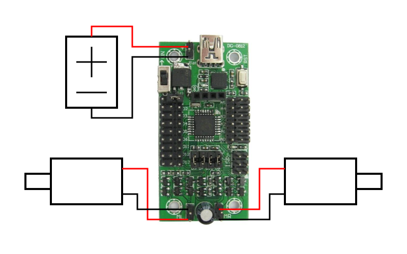
Circuit diagram
The Mini Driver uses 4 of the Atmega8′s digital pins to control its 2 H-bridges. Each H bridge is controlled by a direction pin, and a PWM pin that determines the speed at which the motor turns. The H-bridges are connected to the Atmega8 using 4 jumpers. if you don’t need to use the H-bridges then you can remove the jumpers and use the digital pins for something else.
The pins that the control the H-bridges are as follows
- D7 controls the direction of the left motor
- D9 controls the speed of the left motor
- D8 controls the direction of the right motor
- D10 controls the speed of the right motor
Programming the Mini Driver
The Mini Driver can be easily programmed by connecting it to your computer with a USB cable, and using the standard Arduino IDE. In order to get the IDE to recognize the Mini Driver, you should set the board to be an ‘Arduino NG or older w/Atmega8′
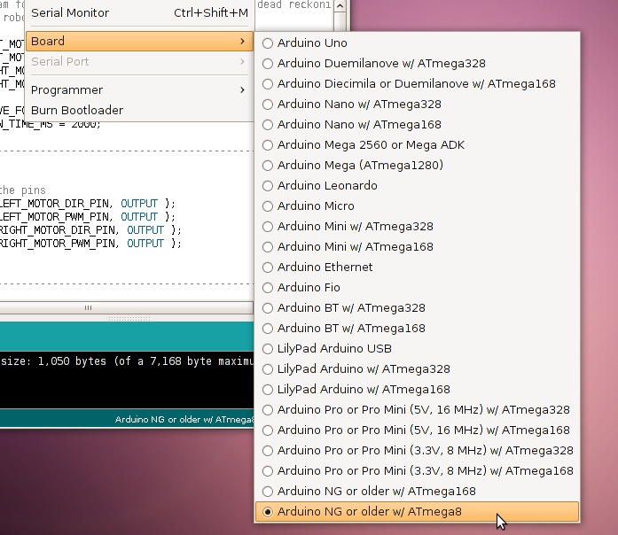
Setting the board type for the Mini Driver
The following sketch is a simple example for how the motors can be used. When attached to the Magician 2WD chassis you should see that the robot drives roughly in a square. ![]()
Note: If the robot doesn’t move, check that the power switch of the Mini Driver is set to ‘On’
// Demo program for the Dagu Arduino Mini Driver. Uses dead reckoning
// to try to drive a robot in a square

const int LEFT_MOTOR_DIR_PIN = 7;
const int LEFT_MOTOR_PWM_PIN = 9;
const int RIGHT_MOTOR_DIR_PIN = 8;
const int RIGHT_MOTOR_PWM_PIN = 10;

const int DRIVE_FORWARD_TIME_MS = 1500;
const int TURN_TIME_MS = 2000;

//----------------------------------------------------------
void setup()
{
    // Setup the pins
    pinMode( LEFT_MOTOR_DIR_PIN, OUTPUT );
    pinMode( LEFT_MOTOR_PWM_PIN, OUTPUT );
    pinMode( RIGHT_MOTOR_DIR_PIN, OUTPUT );
    pinMode( RIGHT_MOTOR_PWM_PIN, OUTPUT );
}

//----------------------------------------------------------
void loop()
{
    // Drive forwards at 100%
    digitalWrite( LEFT_MOTOR_DIR_PIN, HIGH );
    digitalWrite( RIGHT_MOTOR_DIR_PIN, HIGH );
    analogWrite( LEFT_MOTOR_PWM_PIN, 255 );
    analogWrite( RIGHT_MOTOR_PWM_PIN, 255 );
    delay( DRIVE_FORWARD_TIME_MS );

    // Turn left at 50%
    digitalWrite( LEFT_MOTOR_DIR_PIN, HIGH );
    digitalWrite( RIGHT_MOTOR_DIR_PIN, LOW );
    analogWrite( LEFT_MOTOR_PWM_PIN, 128 );
    analogWrite( RIGHT_MOTOR_PWM_PIN, 128 );
    delay( TURN_TIME_MS );
}
Taking Things Further
The mini Driver is ideally suited to controlling servos, and you can attach servos to the column of 3 pin digital connectors down the left hand side. Each set of 3 pins contains a ground, voltage and signal wire which corresponds to the pins of standard RC servos. The supply voltage for the servos is set by the jumper at the top of the digital connectors. It can be set to either 5V, or the battery voltage.
Don’t let the small size of the Mini Driver fool you. With a peak current of 2A for each motor channel, the Mini Driver is capable of driving chassis like the Dagu Rover 5 chassis, and can push some pretty heavy weights (as shown here).
Another thing you can do with the Mini Driver is control it remotely by adding on the Dagu Arduino Bluetooth Module which plugs straight in.
Hi,
I see on the board of Mini-driver has some slots for analog inputs, right (A0, A1, A2, A3, A4, A5) ? I would like to add some IR range finder sensors to my robots; but GPIOs of RPi do not accept analog signals, so I wonder if the mini-driver accepts analog sensors (for example http://www.robot-electronics.co.uk/acatalog/InfraRed_Rangers.html)
Thanks!
Hi Phong,
Yes, the mini driver does accept analog inputs and should work fine with that sensor. To get the analog inputs to the Pi you would need to write a little program from the mini driver that reads the analog inputs and sends them to the Pi. This is essentially the approach that we’ve taken for our Raspberry Pi robot.
Regards
Alan
Hi Alan,
Thank you for the answer. I hope there will be enough slots on the mini-driver and GPIO’s RPi for 2 infrareds, one ultrasonic, two wheel encoders, and a magnetometer. I will have more questions when sensors arrive.
In fact your software is very well written with clear comments. I have a plan to write some more motrol control function that specify the running time (right now the motors stop after a timeout period). When I have the wheel encoder then I can interpret motor speed to rotation angle and vice versa. Why don’t you host your code on GitHub so that many people may folk it? May I repost your code onto that?
Best,
Phong
Hi Phong,
We do have some Github repositories, but I mainly chose Bitbucket because we can work on repositories in private first before ‘releasing’ them. People can still fork the code on Bitbucket but it doesn’t seem to be as popular as Github. No problems with you uploading the code to Github, the more people using it the better.
Regards
Alan
Hi, it’s me again
I just bought a Bluetooth module and plugged it to the mini-driver. Now I want to use my cellphone to controll the bot as what you did with Adventure Bot. Because my starting point is the RPi robot kit, I go into the library raspberry_pi_camera_bot and found the subdir mini_driver_firmware, in which the file .ino is placed. I made some changes in the source file .ino (as what you did with Adventure Bot) but don’t know an “official way” to upload the driver onto the ATmega8 chip. My current way of doing this is:
Run python on the RPi side, then load the mini_driver, and open a connection:
import mini_driver
driver = mini_driver.MiniDriver()
connected = driver.connect()
and check the TRUE value of the connected variable.
So using this way, is it loaded permanently onto the chip? I know that one can use Arduino IDE or Ino to compile and upload the code, but I see you have a more convenient solution based on Python.
Although my cellphone can attach to the bluetooth card (the LED stops blinking), commands fired from MOBOT BTCar have no effect on my robot (Forward, Backward,…). Of course I set configuration on which character is sent when a command is pressed. I would like to ask for a debugging solution with the mini-driver, says, outputs to USB port, or controlling a LED via digital/analog pins, or whatever else.
Thank you!
Forget my questions, I have solved it. Thank you. Just a problem, the SoftwareSerial library seems being incompatible with ATmega8, i.e I could not compilea program using SoftwareSerial.h on Arduino IDE with the selected hardware.
Hi,
I could not use the library SoftwareSerial for this mini-driver ATmega8. Whenever I have
#include
The compiler (Arduino 1.6) outputs the following errors:
C:\Program Files\Arduino\hardware\arduino\avr\libraries\SoftwareSerial\SoftwareSerial.cpp: In member function ‘void SoftwareSerial::begin(long int)’:
C:\Program Files\Arduino\hardware\arduino\avr\variants\standard/pins_arduino.h:58:62: error: ‘PCICR’ was not declared in this scope
#define digitalPinToPCICR(p) (((p) >= 0 && (p) <= 21) ? (&PCICR) : ((uint8_t *)0))
Studying on the Internet and I found that SoftwareSerial is not available for ATmega8 chip! See this:
https://maitreyanaik.wordpress.com/tag/arduino-ng/
and this:
http://forum.arduino.cc/index.php?topic=304335.0
and this too:
http://letsmakerobots.com/dagu-mini-driver-hc05
If this is true, it's really bad. I think you may have solution for this problem?
Dear Phong,
First of all. Very sorry for the big delay in replying to your questions. It’s been really hectic here and I haven’t been checking blog comments enough.
In answer to your questions, the Python software we provide for our robot kit uses the Ino program behind the scenes to upload a sketch. With regards to using software serial, that is a bit annoying, it looks like it can’t be used because the Atmega8 doesn’t have pin change interrupts.
You could perhaps modfiy the library to use the interrupts on pins D2 and D3, but maybe there’s an alternative to using SoftwareSerial. Why are you trying to use SoftwareSerial? If I was controlling the MiniDriver with bluetooth I would just use normal Serial and then you have to unplug the bluetooth module whilst programming the mini driver. Alternatively, it might be possible to use a different protocol like SPI to get serial and another communication protocol to work.
If you can give me an idea of the type of program you’re trying to write then I’ll do my best to help.
Regards
Alan
I just want to write a simple communication between an adroid phone and the mini-driver, or between two mini-drivers (robots interaction). It sounds good as you say I can use Serial for the bluetooth. Can you give me a snippet code doing this, or a link? I use SoftwareSerial just because a lot of tutorials about getting HC-05 work with arduino are using SoftwareSerial so do I
Hi Phong,
You basically just need to replace all references to BluetoothSerial to just be Serial. This code adapted from our bluetooth robot tutorial should work on your Mini Driver.
Regards
Alan
const int LEFT_MOTOR_DIR_PIN = 7;

const int LEFT_MOTOR_PWM_PIN = 9;

const int RIGHT_MOTOR_DIR_PIN = 8;

const int RIGHT_MOTOR_PWM_PIN = 10;
// Enums for drive and turning direction
enum eDriveDirection
{
eDD_ForwardTurbo,
eDD_Forward,
eDD_Backward,
eDD_Stopped
};
enum eTurnDirection
{
eTD_Left,
eTD_Right,
eTD_None
};
// Constants
const unsigned long NO_COMMAND_STOP_TIME_MS = 2000; // Stop if we don't get a command
// in this many milliseconds
const int MOTOR_SPEEDS[ 4 ][ 3 ][ 2 ] = // Drive direction, turn direction, motor (Left or Right)
{
// Left Right No Turn
{ { -50, 50 }, { 50, -50 }, { 100, 100 } }, // Forward Turbo
{ { -50, 50 }, { 50, -50 }, { 50, 50 } }, // Forward
{ { -50, 50 }, { 50, -50 }, { -50, -50 } }, // Backward
{ { -50, 50 }, { 50, -50 }, { 0, 0 } }, // Stopped
};
// Global variables
eTurnDirection gTurnDirection = eTD_None;
eDriveDirection gDriveDirection = eDD_Stopped;
unsigned long gLastCommandTime = 0;
//--------------------------------------------------------------------------------------------------
void setup()
{
// Setup the pins
pinMode( LEFT_MOTOR_DIR_PIN, OUTPUT );
pinMode( LEFT_MOTOR_PWM_PIN, OUTPUT );
pinMode( RIGHT_MOTOR_DIR_PIN, OUTPUT );
pinMode( RIGHT_MOTOR_PWM_PIN, OUTPUT );
// Initialise serial communication for bluetooth at 9600 bits per second
Serial.begin( 9600 );
}
//--------------------------------------------------------------------------------------------------
void loop()
{
unsigned long curTime = millis();
// Update the software state in response to serial commands
if ( Serial.available() )
{
char command = Serial.read();
boolean bGotCommand = true;
if ( 'f' == command ) // Forward
{
gDriveDirection = eDD_Forward;
}
else if ( 'b' == command ) // Backward
{
gDriveDirection = eDD_Backward;
}
else if ( 't' == command ) // Turbo
{
gDriveDirection = eDD_ForwardTurbo;
}
else if ( 'z' == command || 'y' == command || 'x' == command ) // Stop forward, backward or turbo
{
gDriveDirection = eDD_Stopped;
}
else if ( 'l' == command ) // Go right // Note: Not a bug, just how MOBOT BTCar is
{ // setup by default
gTurnDirection = eTD_Right;
}
else if ( 'r' == command ) // Go left
{
gTurnDirection = eTD_Left;
}
else if ( 'v' == command ) // Stop turn
{
gTurnDirection = eTD_None;
}
else if ( 's' == command ) // Full stop
{
gTurnDirection = eTD_None;
gDriveDirection = eDD_Stopped;
}
else
{
// Unrecognised command
bGotCommand = false;
}
if ( bGotCommand )
{
gLastCommandTime = curTime;
}
}
// Stop the robot if we don't get a command for a while
if ( curTime - gLastCommandTime > NO_COMMAND_STOP_TIME_MS )
{
gTurnDirection = eTD_None;
gDriveDirection = eDD_Stopped;
}
// Calculate the motor speeds and set them
int leftMotorSpeed = MOTOR_SPEEDS[ gDriveDirection ][ gTurnDirection ][ 0 ];
int rightMotorSpeed = MOTOR_SPEEDS[ gDriveDirection ][ gTurnDirection ][ 1 ];
digitalWrite( LEFT_MOTOR_DIR_PIN, ( leftMotorSpeed > 0 ? HIGH : LOW ) );
digitalWrite( RIGHT_MOTOR_DIR_PIN, ( rightMotorSpeed > 0 ? HIGH : LOW ) );
int leftMotorPWM = constrain( (((float)abs( leftMotorSpeed ))/100.0f) * 255.0f, 0, 255 );
int rightMotorPWM = constrain( (((float)abs( leftMotorSpeed ))/100.0f) * 255.0f, 0, 255 );
analogWrite( LEFT_MOTOR_PWM_PIN, leftMotorPWM );
analogWrite( RIGHT_MOTOR_PWM_PIN, rightMotorPWM );
}
Sorry, the formatting for that code is pretty rubbish, but you should hopefully get the idea.
Regards
Alan
I have time today to try your instruction. Similarly to your code, I try a very simple code to test the HC-06:
int led = 13;
// the setup routine runs once when you press reset:
void setup() {
// initialize the digital pin as an output.
pinMode(led, OUTPUT);
Serial.begin(57600);
}
// the loop routine runs over and over again forever:
void loop() {
if (Serial.available()) {
char cmd = Serial.read();
if (‘f’ == cmd){
Serial.println(“Command recognized”);
digitalWrite(led, HIGH); // turn the LED on (HIGH is the voltage level)
delay(1000); // wait for a second
digitalWrite(led, LOW); // turn the LED off by making the voltage LOW
}
else
{
Serial.println(“Unrecognized command”);
digitalWrite(led, HIGH); // turn the LED on (HIGH is the voltage level)
delay(100); // wait for a second
digitalWrite(led, LOW); // turn the LED off by making the voltage LOW
}
}
}
So I detach the HC-06 and attach the USB2Serial cable into the mini driver and upload the code above. First I test the serial connection by openning the Serial Monitor and type “f”, then the blue LED on the mini driver blinks for a second. So the (wired) serial connection works!
Then I detach the USB cable and attach the HC-06. The board is powered by a battery source (5V 1.2amp). Now the bluetooth LED is blinking. I either use BT BotCar or BlueTerm on my smartphone to bind with the HC-06. The bluetooth LED stop blinking; this means the pairing is successful. Then I type “f” but see no respond on the LED of the mini driver. I guess the Serial connection is not available.
I set the baud rate to either 9600 or 57600 but no help.
Hi Phong,
Try leaving the HC-06 detached whilst you get serial to work. Shouldn’t have any effect, but perhaps it’s wired the wrong way round.
Please double check the connection of the bluetooth module to check that it is plugged into the mini driver the correct way round.
In the mini driver code, the baud rate should be 9600 (Serial.begin(9600)). This is because the baud rate of the bluetooth modules are 9600 by default, although this can be changed later by sending special serial commands.
It might also help if you send data periodically from the mini driver using Serial.println see if you can see anything on your phone.
Regards
Alan
Your advice saved my life
“Please double check the connection of the bluetooth module to check that it is plugged into the mini driver the correct way round.”
I thought that the bluetooth slot is straightforward and just plug the HC-06 in. But I was wrong. The RX on the board has to be connected with the TX of the HC-06 and the TX (board) -> RX (HC-06). I learned this from a blogpost on Sparkfun:
https://learn.sparkfun.com/tutorials/serial-communication
It is necessary to wire the bluetooth module using jumperwires (with or without breadboard) and not directly to the mini-driver.
Now it works like charms.
Thank you!
Aha,
Yes, this shouldn’t happen with the Dagu version of the bluetooth module that we sell, which is designed specifically for the Mini Driver, but I can see how it might cause a problem for the HC-06.
Glad you got it working.
Regards
Alan
Yeah. I separately bought this module from Ebay after noticing that your mini-driver is bluetooth capable.
Phong.
Hi, I run into another trouble
I have two dagu mini-drivers, an old (called it A) and a newer one (called it B). The A works fine for my 2WD Magician chassis robot. Recently I want to plug some more sensors and servors to A so that I reprogram the sketch. I tried to upload but failed many times. A very simple program is Blink (LED); I can upload smoothly to the B but not to A. The message from A is:
avrdude: stk500_recv(): programmer is not responding
Then I suspect that the bootloader of A is problematic (since there are several times the power of the robot suddenly off, maybe due to insufficient voltage or current). I followed your instruction to make B as a programmer to upload the bootloader via ISP to the A. All the parameters are correctly set: Board: Arduino NG/older atmega8, Port: /dev/ttyUSB0, Programmer: Arduino as ISP. I tried to clikc on Burn Bootloader many many times but they constantly talk to me:
avrdude: Yikes! Invalid device signature.
Double check connections and try again, or use -F to override this check.
One of out one hundred times the burning is silent and just output:
Binary sketch size: 4,884 bytes (of a 7,168 byte maximum)
I thought the bootloader is already on its place so I try to upload sketches to it using normal serial USB port but again:
avrdude: stk500_recv(): programmer is not responding
I have tried:
-Arduino IDE 1.0.4 and Arduino IDE 1.6.0 too, but no difference.
-Supply the USB with more power (I use two USB ports for instance) but no help
This is my setup to burn the bootloader to A via ISP, using B as the programmer:
https://drive.google.com/open?id=0B26_kd-0bahhNzVncVFRTlo0aEU&authuser=0
If I upload the simple Blink code to the programmer B, then after wiring the ISP, I have the both drivers blinking synchronously. That means the wiring is correct ?
https://drive.google.com/open?id=0B26_kd-0bahhTkgxTW5Hemw3TWc&authuser=0
This is the ISP connect on the programmer side:
https://drive.google.com/open?id=0B26_kd-0bahhMm5EWXQ1SzkwZU0&authuser=0
According to your instruction, one has to remove the jumper at D10 and plug the reset wire there, right?
and the ISP connection on the driver A:
https://drive.google.com/open?id=0B26_kd-0bahhTkgxTW5Hemw3TWc&authuser=0
Hi Phong,
Sorry for the delayed reply.
I have managed to flash an Arduino with a mini driver, but it was a while ago, and I remember it being tricky. Probably the best thing would be, if you have an Arduino, such as an UNO lying around, to use that, as it’s a bit easier. Alternatively, if you have some wires and some 1K resistors to use for current limiting you can use your Raspberry Pi by following the instructions here.
Hope that helps.
Regards
Alan
Hi,
What a brilliant advice! I have another RPi card and so I got to connect 4 GPIOs on RPi to SPI port of mini-driver and with resistors in between. The mini-driver is new like out of the box now. Thank you!
By the way, in order to avoid future corruptions of the boot loader, I guess I have to guarantee the supplying voltage is between 5V and 9V? How about lower than 5V?
In particular, I have two robots:
(1) One is the Magician chassis kit bought from this store. I use the TeckNet powerbank if 5V+2.1A for the RPi and 5V+1A for the mini-driver. Sometimes the robot suddenly power off if it moves quickly from idle. The PWR LED of RPi is frequently blinking (it means lack of V).
(2) Another one is assembled from one mini-driver and the Tamiya tank chassis. The mini-driver is responsible for the 2x motors, 2x servos, 1x bluetooh HC-05, and 1x IR Sharp sensor. Is there any problem if I power this whole stuff with 4x AA rechargeable piles?
Best regards,
Phong
Hi Phong,
I think that keeping the supply voltage in the range of 5V to 9V is a good idea, but I’m not 100% sure on what the cause of bootloader corruption could be. It seems to be quite rare, but it does occasionally happen.
For your robots, I’ve seen the PWR LED blinking on B+ and Pi 2 robots, but haven’t had the power off in response to a quick move, this would probably indicate that the motors are drawing too much current so it might be worth checking that they’re not obstructed in any way. Also, it might be worth swapping the powerbank conenctors around so that the 2.1A connector powers the mini driver, and the 1A connector powers the Pi. On the old model B we seemed to need the 2.1A connector to power both the Pi and wifi, but with the new B+ or Pi 2, I think that as long as you’re using a low power WiFi dongle like the edimax, you might be able to run the Pi and WiFi off 1A.
For your second robot, if there’s no Pi involved then 4xAA rechargeable batteries should be perfect.
Regards
Alan
Yeah, I have been swapping those outputs for more stable robot running. I just read somewhere that keeping too long a voltage under 5V for arduino devices may cause their bootloaders to be damaged.
Again, I appreciate very much your kindness and helpful answers.
Phong.