
OSH Park
Profile for fisher0251
Shared projects
555 LED Flasher
by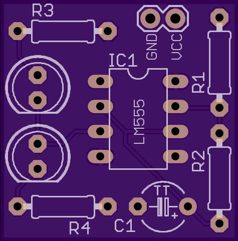
2
layer board of
0.95x0.96
inches
(24.13x24.46
mm).
Shared on
September 14th, 2015 19:03.
Simple 555 timer circuit to flash 2 LEDs. R1. R2 and C1 set the timer frequency and duty cycle. R3 and R4 limit the current through each LED.
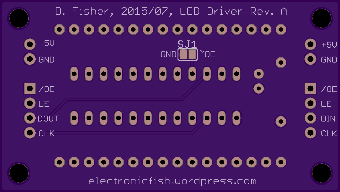
LED Driver Rev. A
by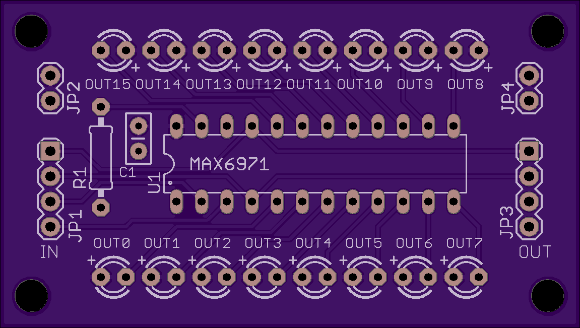
2
layer board of
2.30x1.30
inches
(58.42x33.02
mm).
Shared on
July 3rd, 2015 21:18.
LED driver board for the MAX6971. This chip operates as a shift register, so the boards are designed to connect together in series with DOUT of the earlier board connected to DIN of the later.
The chip can be enabled with a PWM signal on ~OE to dim the LEDs. To permanently enable the chip, solder ~OE to GND at SJ1 on the bottom of the board.
LED connections and header pins are set back 0.2" from the board’s edge to allow space for the option of Molex wire-to-board connectors.
This board has been successfully built and tested.
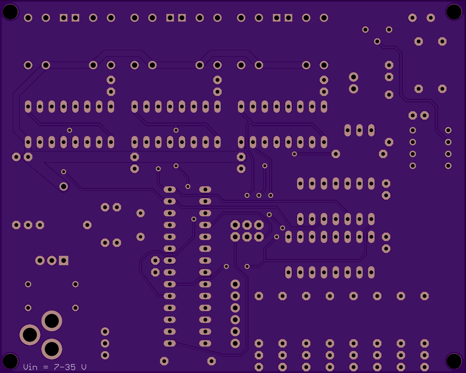
Omnibot control board, Rev. A
by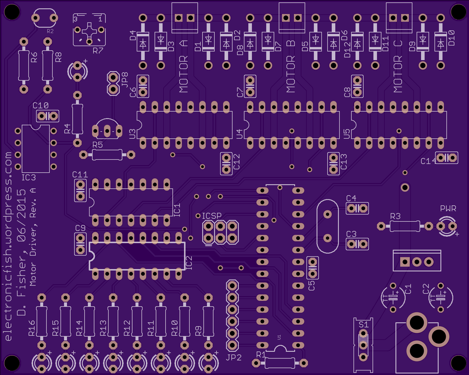
2
layer board of
3.94x3.15
inches
(100.00x80.01
mm).
Shared on
June 15th, 2015 03:56.
ATMEGA328P onboard control for 3 DC brushed motors. This is my version of a control board for this project from Make Magazine. It uses dual H-bridges ICs (SN754410) to drive each motor (channels are doubled for up to 2A continuous current per motor, 4A peak for very short times). Power LED. Also 8 LEDs run by a 74LS595 shift register for “blinky” fun! Photoresistor allows for a laser hit to be detected and affect the omnibot.
This board has been successfully built and tested. It needs an extra +5V/GND header added to provide power to the RC receiver (and servo).
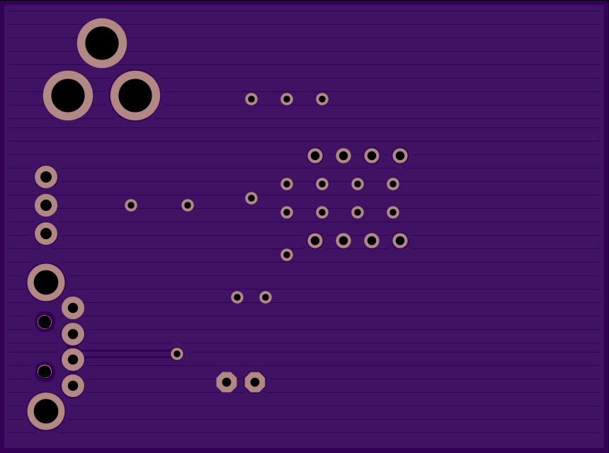
DCDC Buck Converter USB Charger
by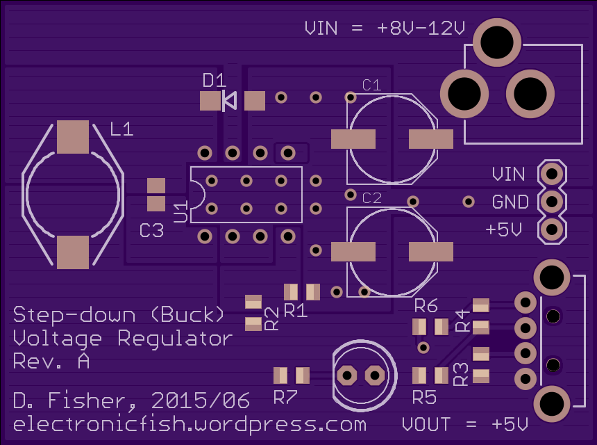
2
layer board of
2.15x1.60
inches
(54.61x40.64
mm).
Shared on
June 8th, 2015 04:41.
I designed this as a universal USB charger for phones and tablets. Vin = +8-12V, Vout = +5V @ 1A. I’m using one or two 8-AA battery packs for Vin depending on how much current is required at the output.
It uses the LM2675-ADJ from TI as U1. By choosing the appropriate inductor L1, input and output capacitors C1 and C2, and feedback resistors R1 and R2, this can be configured for other output voltages. R3 to R6 set voltages on the D- and D+ USB lines to allow for Apple device charging up to 1A (as discussed by Adafruit’s Lady Ada here).
Components: LM2675-ADJ, PDIP-8 package L1 = 33uH, CoilCraft DO3316P-333 C1 = 150uF, low-ESR aluminum electrolytic cap, Panasonic EEE-FP1V151AP C2 = 100uF, low-ESR aluminum electrolytic cap, Panasonic EEE-FP1V101AP C3 = 0.01uF, 0805 ceramic cap D1 = 20V 3A Schottky diode, DO214AC package R1 through R6 all 0805, 1%: R1 = 1k, R2 = 3.16k, R3 = 43k, R4 = R6 = 49.9k, R5 = 75k R7 = 220ohm, 0805, 5%
Vin is designed for a 5.5mm DC barrel jack like this one.
The USB jack is a common USB-A female through-hole plug.
This board has been tested at +5V, 1A output. The LED polarity has been reversed from what is indicated on the silkscreen.