OSH Park
Shared projects
s006 circuit
by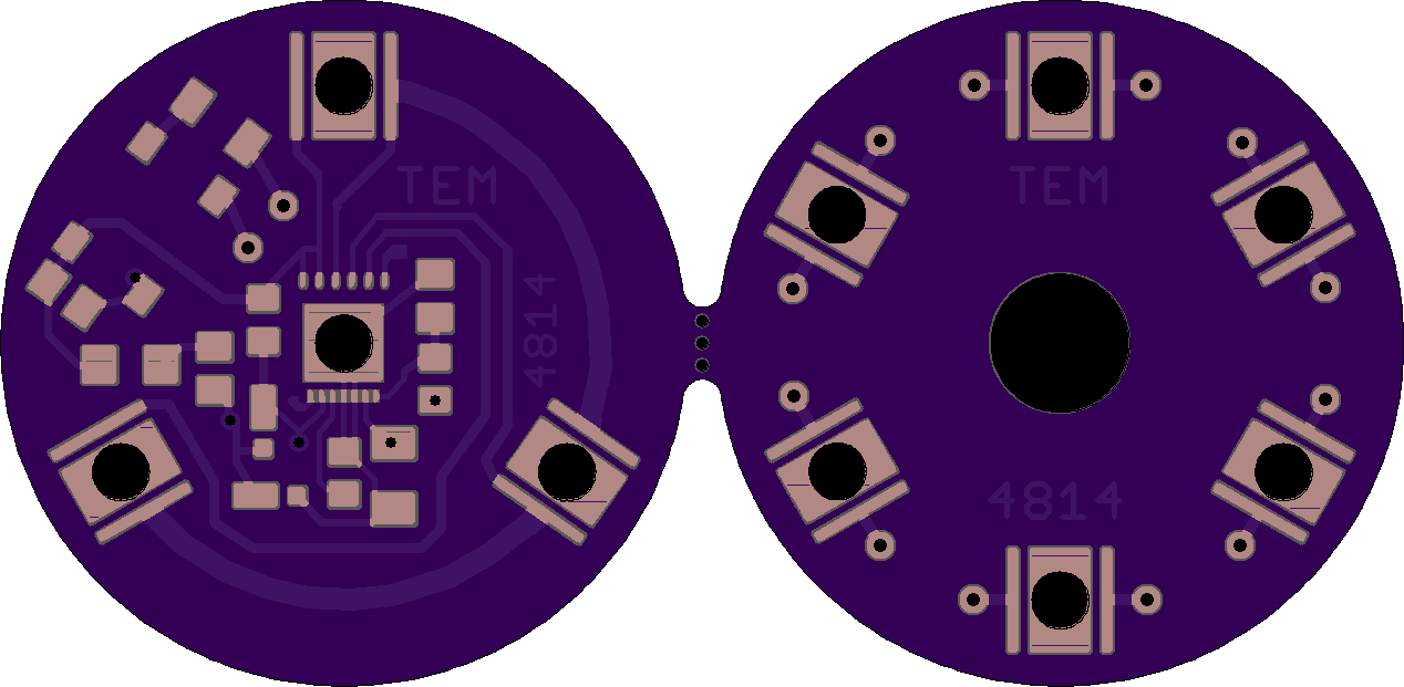
2
layer board of
2.54x1.24
inches
(64.39x31.52
mm).
Shared on
September 20th, 2015 21:06.
s006 driver, cree xmlhvw, powerpeg
SatNOGS Rotator Encoder
by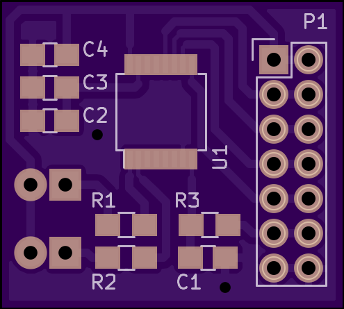
2
layer board of
0.99x0.89
inches
(25.17x22.63
mm).
Shared on
September 20th, 2015 20:16.
Encoder PCB for SatNOGS rotator v3
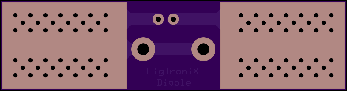
FigTroniX - Dipole starter. - KD5VMF
by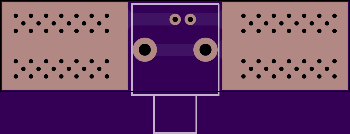
2
layer board of
2.31x0.61
inches
(58.57x15.39
mm).
Shared on
September 20th, 2015 18:09.
KD5VMF@GMAIL.COM
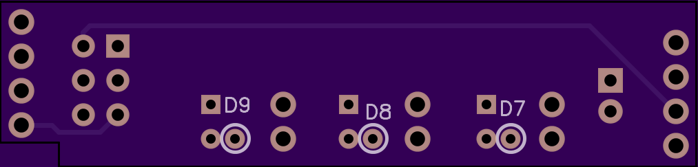
ArduinoISP header shield v0.2(tested)
by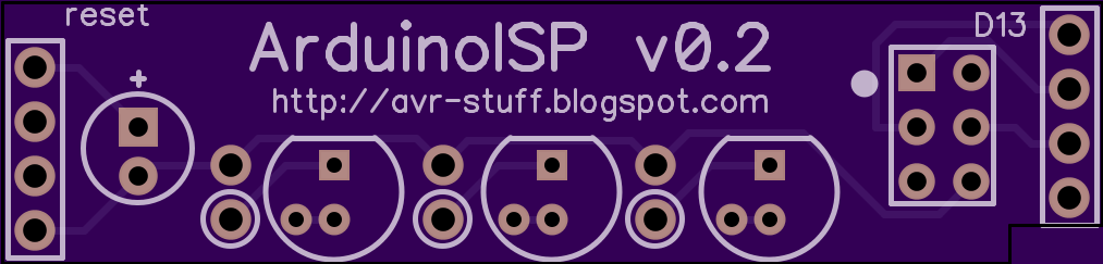
2
layer board of
2.03x0.49
inches
(51.46x12.34
mm).
Shared on
September 20th, 2015 00:41.
Fixed the 2x3 header and added blinky lights.
Blog post 1 Blog post 2 I was looking for an “Arduino as ISP” shield to program a few dev boards, but the shields are all for IC sockets. I wanted simple, and cheap.
This will need a 2x3 IDC ribbon cable and a way to get it on the other side, adafruit has the cable and the breakout for all of $3 if you want to go that route, don’t forget a few male headers if you need them.
There is a footprint for a 10uF cap if it’s needed, i didn’t but it’s there if you do. The led’s are optional, but who doesn’t like blinking stuff. They fit on the board and didn’t cost extra. I designed them to work with wires dropping down hence the silk on the bottom. you can’t really see it but the board is notched on the right for access to pin 9. IT’s enough for a breadboard wire to work well, the hole for the wire on the bottom is tight for 22(7) I snipped a strand off to make it fit better.
Hint: this isn’t straight across. You’ll need to solder the headers with it on the arduino. the header holes allow for enough play. Once soldered it’s perfect and slides right in and out.
Dip trace file for the board is in the zip.

TQFN_6955
by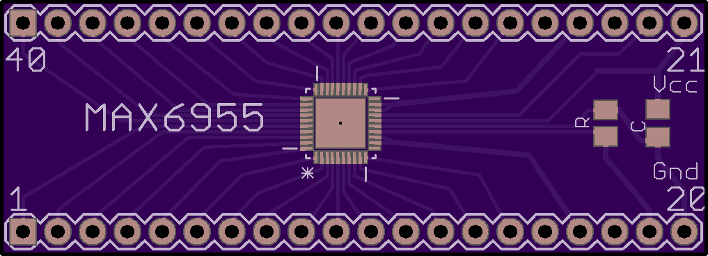
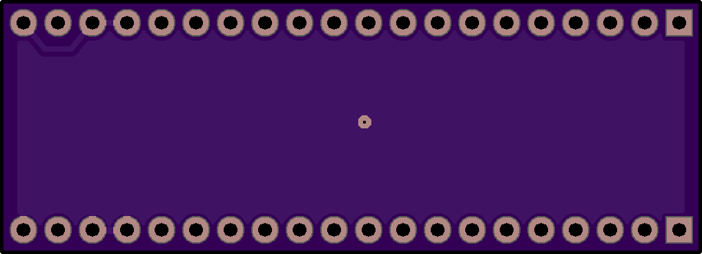
2
layer board of
2.04x0.74
inches
(51.71x18.69
mm).
Shared on
September 19th, 2015 22:49.
Breakout for MAX6955-TQFN.
Details here: http://timewitharduino.blogspot.ca/2015/07/experimenting-with-max6955.html