OSH Park
Shared projects
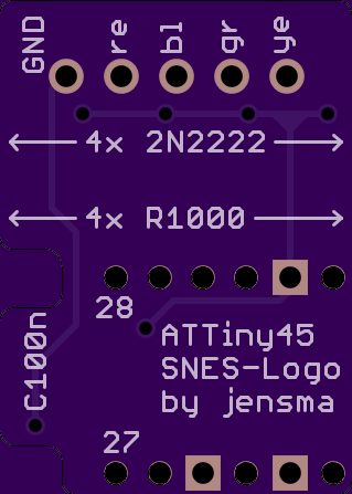
SNES-LED logo base
by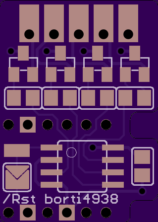
2
layer board of
0.64x0.89
inches
(16.21x22.71
mm).
Shared on
August 26th, 2015 11:31.
Idea and ATTiny-Code by jensma @ circuit-board.de http://circuit-board.de/forum/index.php/Thread/7573-Super-Nintendo-Beleuchtetes-animiertes-Logo/
Last change: I moved resistors for the LEDs to the PCB of the LEDs.
Parts needed:
- 4x 1kOhm (0805 package)
- 4x 2N2222 (SOT23 package)
- 1x 100nF/50V (0805 package)
- 1x ATTiny45-20SU (SOIC-8 package)
Code for the ATTiny45: http://circuit-board.de/forum/index.php/Attachment/529-sneslogo-attiny45-zip/
Fuses:
- low: 0xe2
- high: 0xdf
PCB has to be soldered to the Expansion port.
/RST is to reinitiate the logo animation. Either close the jumper (animation on every system reset) or connect the pad with the CIC-lock pin10 (animation only on user reset). NEVER do both!!!
Looking for the counterpart? Here it is: https://oshpark.com/shared_projects/8jJG2ZIz
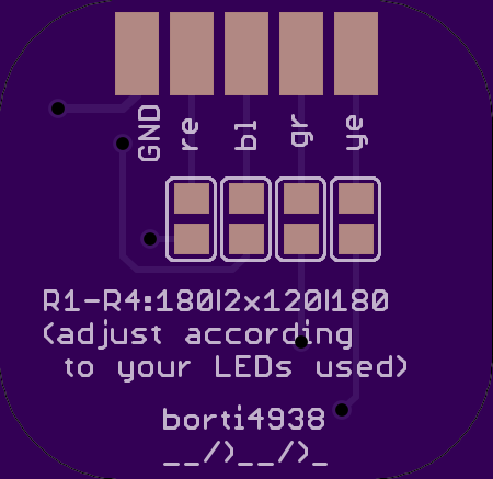
SNES-LED-Logo
by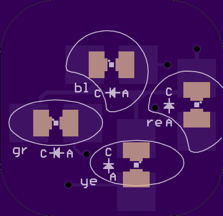
2
layer board of
0.90x0.88
inches
(22.89x22.23
mm).
Shared on
August 26th, 2015 11:31.
Last changes: Move resistors for LEDs to the LED-PCB. LEDs in 0805 package or P-LCC-2 package can be used.
Parts needed:
- 4x resistors (values according the LEDs used, 0805 or P-LCC-2 package)
- 4x LEDs in red, green, yellow and blue
Install the PCB directly below the SNES logo. Drill holes in advance.
More information needed:
http://circuit-board.de/forum/index.php/Thread/7573-Super-Nintendo-Beleuchtetes-animiertes-Logo/
Looking for the counterpart? Here it is: https://oshpark.com/shared_projects/GaFln6YV
Audio Splitter V2
by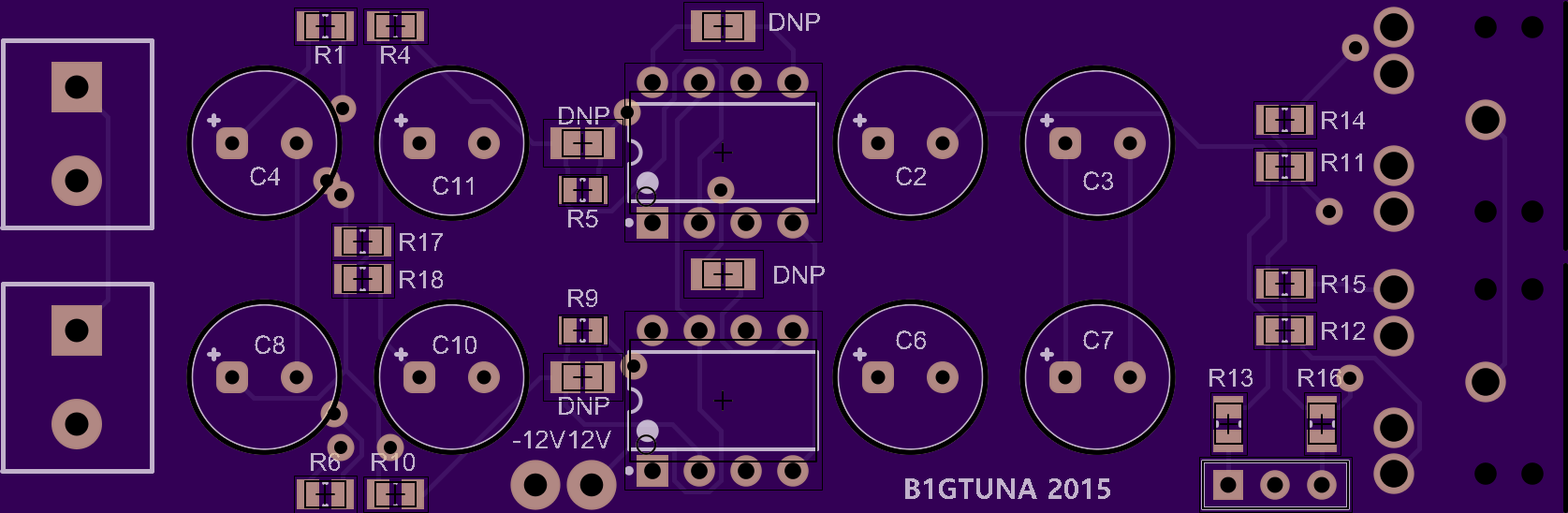
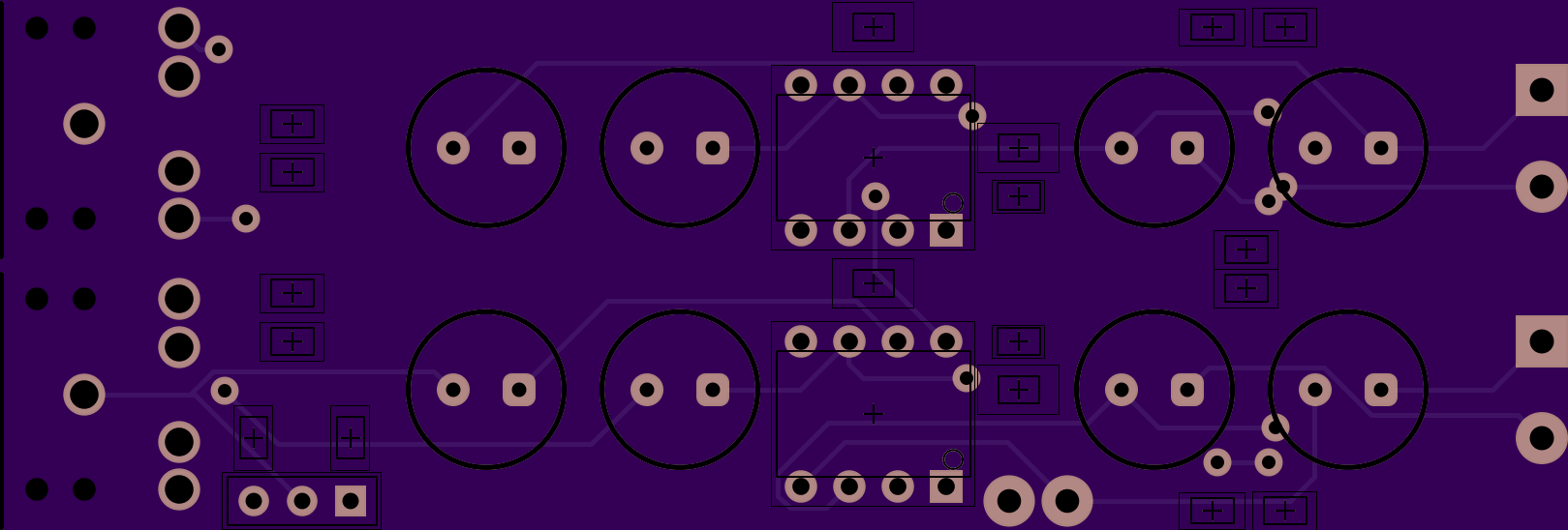
2
layer board of
2.95x1.10
inches
(74.96x27.84
mm).
Shared on
August 26th, 2015 09:54.
ESP8266-01 minimal node v1
by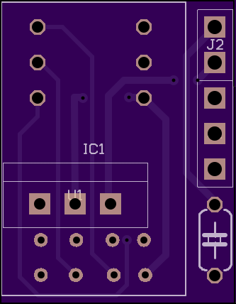
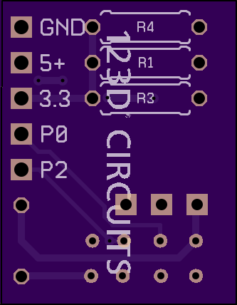
2
layer board of
0.67x0.86
inches
(16.92x21.77
mm).
Shared on
August 26th, 2015 06:05.
Circuit for minimal setup of ESP8266-01 with 3.3 regulator and P0/P2 exposed
15214^0
by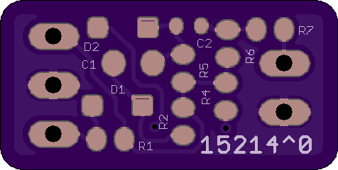
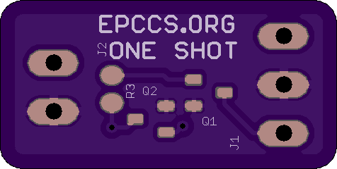
2
layer board of
0.95x0.48
inches
(24.13x12.12
mm).
Shared on
August 26th, 2015 05:45.
OneShot
Simple Monostable Multivibrator Circuit that functions as a one shot that ignores the switch during activation time, e.g. further switch closures do not reset the timing circuit. .