OSH Park
Shared projects
ATtiny841-ISP
by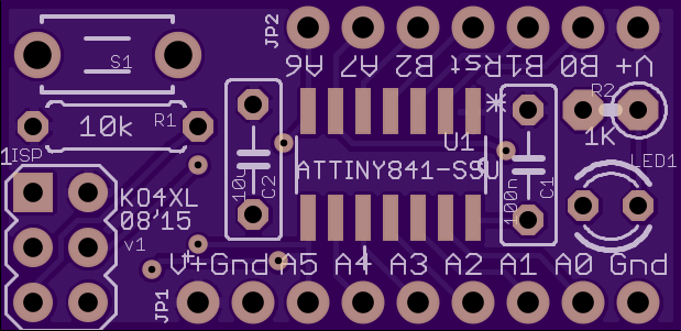
2
layer board of
1.24x0.60
inches
(31.45x15.27
mm).
Shared on
August 25th, 2015 03:06.
Prototyping module for ATtiny441 or ATtiny841 with ISP header.
Breakout board - buttons and LEDs
by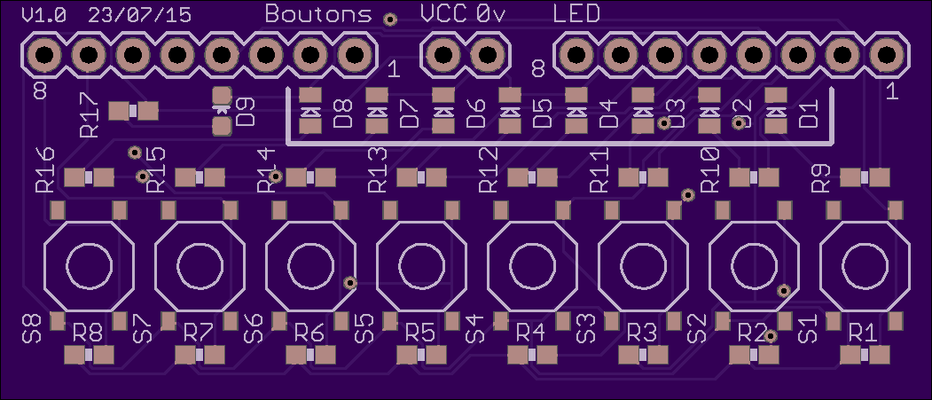
2
layer board of
2.10x0.90
inches
(53.37x22.89
mm).
Shared on
August 24th, 2015 20:22.
8 SMD push-buttons and 8 SMD LEDs. The LEDs are common cathode tied to ground through a current limiting resistor. The push buttons are pull-down to ground. You can get some informations about this on this page : https://hackaday.io/project/7188-8-buttons-8-leds-breakout-board
zum scan
by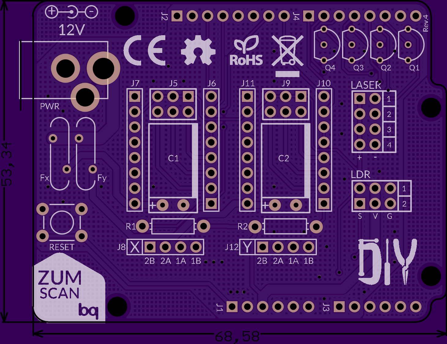
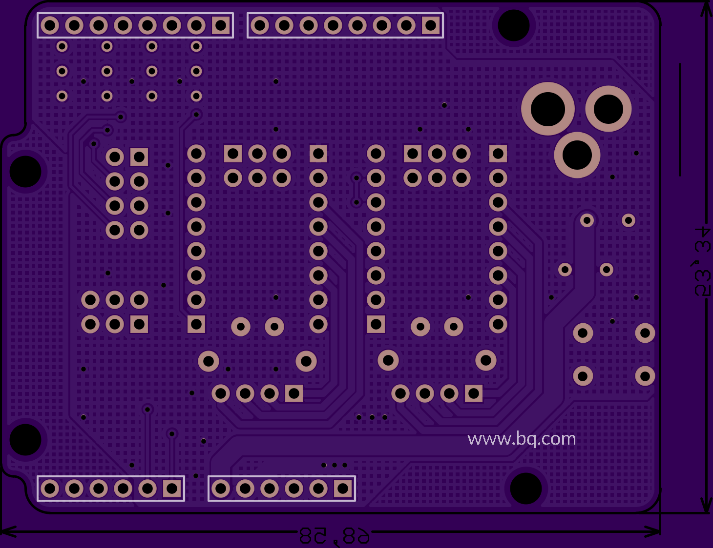
2
layer board of
2.92x2.25
inches
(74.19x57.12
mm).
Shared on
August 24th, 2015 19:49.
ledbrick pwm ble 0.2
by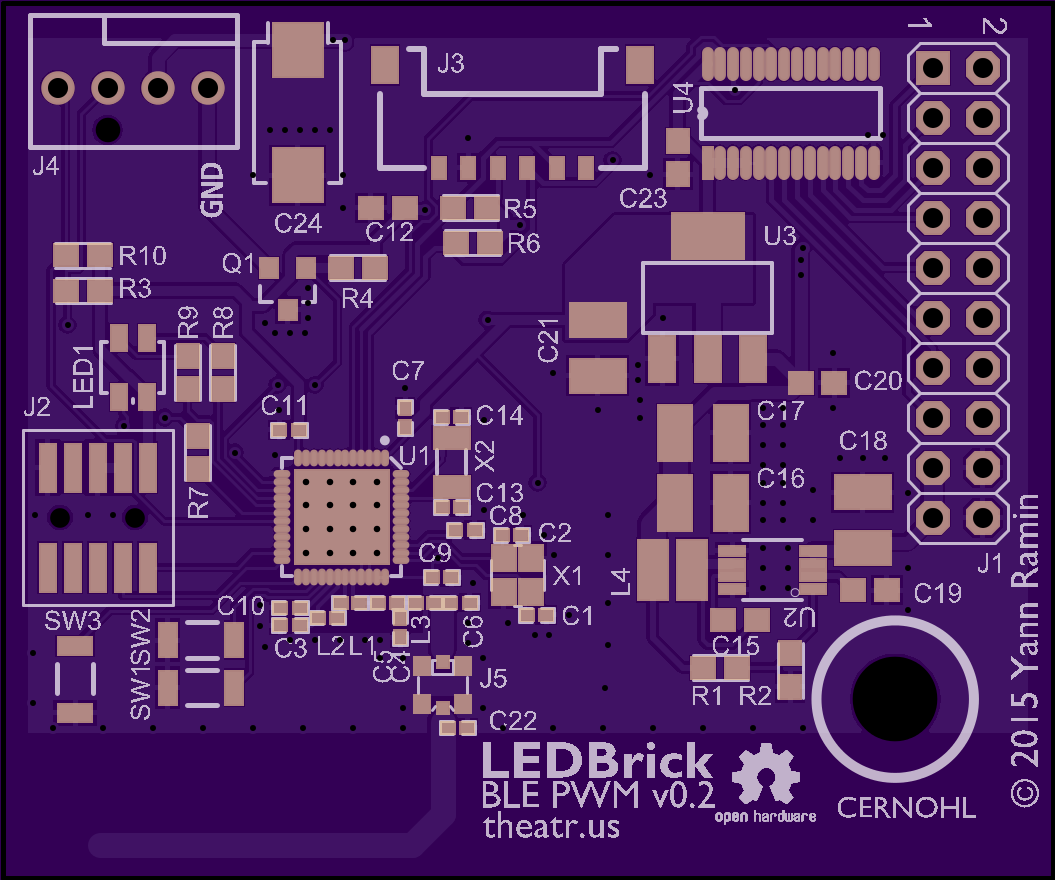
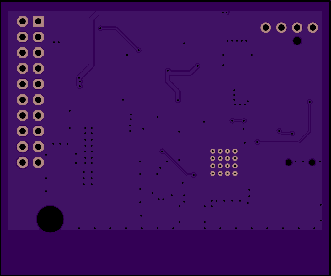
2
layer board of
2.11x1.76
inches
(53.62x44.70
mm).
Shared on
August 24th, 2015 05:24.
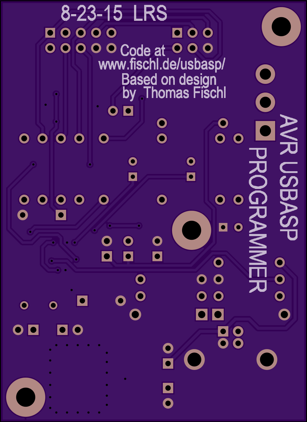
AVR USBASP_PROGRAMMER V1.0
by
2
layer board of
2.01x2.76
inches
(50.95x70.00
mm).
Shared on
August 24th, 2015 02:02.
A version of the classic Atmel ISP programmer by Thomas Fischl. This one supports 3.3V and 5V operation on the Programmer and Target and has Schottky ESD protection diodes on the 4 main lines for the ISP. Both 6 and 10 pin headers are supported. Mostly thru hole for easy assembly, the ATMega88 is a 32 pin TQFP and should be easy to solder for most people. The ESD diodes are simple SOT23 devices, BAT54C dual types and easy to solder as well. Fischl’s website is noted on the reverse side for all the firmware and operation guidance.
If I can find a way to submit a .pdf of the schematic it will go in here as well.