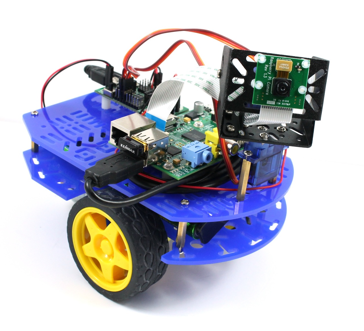
 A Raspberry Pi with a camera, gives you a small, low cost, embedded vision system, but it’s not very mobile. In this tutorial we show you how to fix that by attaching it to a robot to give you a Raspberry Pi camera robot! The robot is WiFi enabled which means you can drive it around using a tablet, phone or computer, using the camera to explore remote areas.
We’ve tried to keep the components for this tutorial as affordable as possible, and as such we’re using the Dagu Arduino Mini Driver to control the motors and servos of the robot. This board also contains a 1A voltage regulator which we can use to power the Pi. Now a limit of 1A is a bit tight for the Pi, but we’ve found that with the right WiFi dongle, the Mini Driver voltage regulator can happily power itself, the Pi, a camera, and WiFi. All the ingredients you need for a camera robot. ![]()
Update: This robot also works with the Model B+ Pi, and the new Raspberry Pi 2. We’ve updated the instructions to reflect this below.
Update: We’ve now changed the robot slightly so that it uses a UBEC to power the Pi. This extends the battery life of the robot, and increases the current limit for the Pi to 3A.
Required Materials
This tutorial uses quite a lot of materials, but if you already have a Raspberry Pi and a Raspberry Pi camera to hand, then it’s probably one of the most affordable camera robots you can build.
Update: We now sell a chassis bundle for this robot in our store. This comes with wires soldered onto the motors and connectors crimped onto all of the wires, which makes the robot much easier to build.
- Dagu Magician 2WD Robot Chassis
- Dagu Arduino Mini Driver Board
- Dagu Sensor Pan/Tilt Kit
- Raspberry Pi Model B, Raspberry Pi Model B+ or a Raspberry Pi 2
- Raspberry Pi Camera Module
- USB WiFi Dongle (we recommend the Edimax EW-7811Un)
- Raspberry Pi Fixing Kit (to mount the Pi on the chassis)
- M2 Spacers, Washers and Screws (to mount the Pan/Tilt kit)
- Sensor Fixing Kit (to mount the camera on the Pan/Tilt Kit)
- Jumper wires to connect motors to the Mini Driver
- Crimp connectors, or alternatively jumper wires for the battery pack
- A USB cable to join the Pi to the Mini Driver – we sell a 1m cable
- 6xAA battery pack – the 4xAA battery pack included with the 2WD chassis just doesn’t provide enough oomph for the Pi)
- 6xAA batteries to power the robot – we recommend NiMh rechargeable batteries – alternatively, you can power the robot with a TeckNet iEP387 USB Power Bank and USB power cable.
- A 3A UBEC for Raspberry Pi to convert the battery voltage to 5V for the Pi
Assembling the Robot
Assemble the the 2WD robot chassis by following the instructions that come with it, and the assembly instructions from this blog post.
Assemble the pan/tilt kit by following its instructions, and then mount it on the chassis using some M3 hex spacers and screws. You may need to widen the holes on the pan servo before the screws will fit, but this can be done fairly easily using a small screwdriver. Update: If you bought a chassis bundle on or after 3rd April 2014 then it should contain M2 hex spacers instead, which are easier to attach to the pan servo. These are used as shown in the pictures below
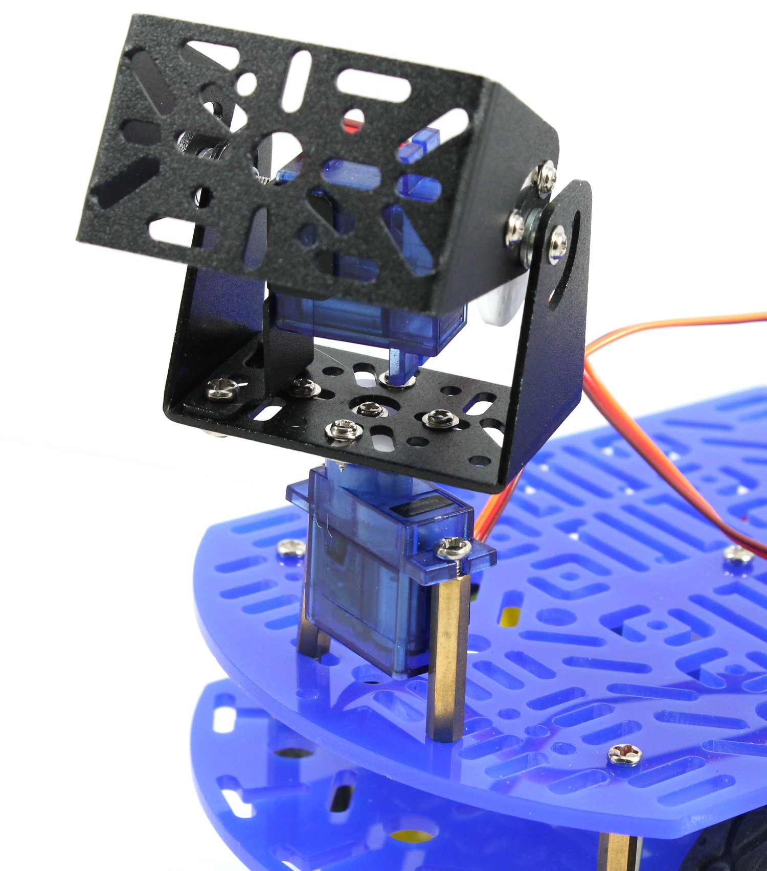
Attach the Pan/Tilt kit as shown (new chassis bundles come with M2 hex spacers, not the M3 hex spacers shown in the image)
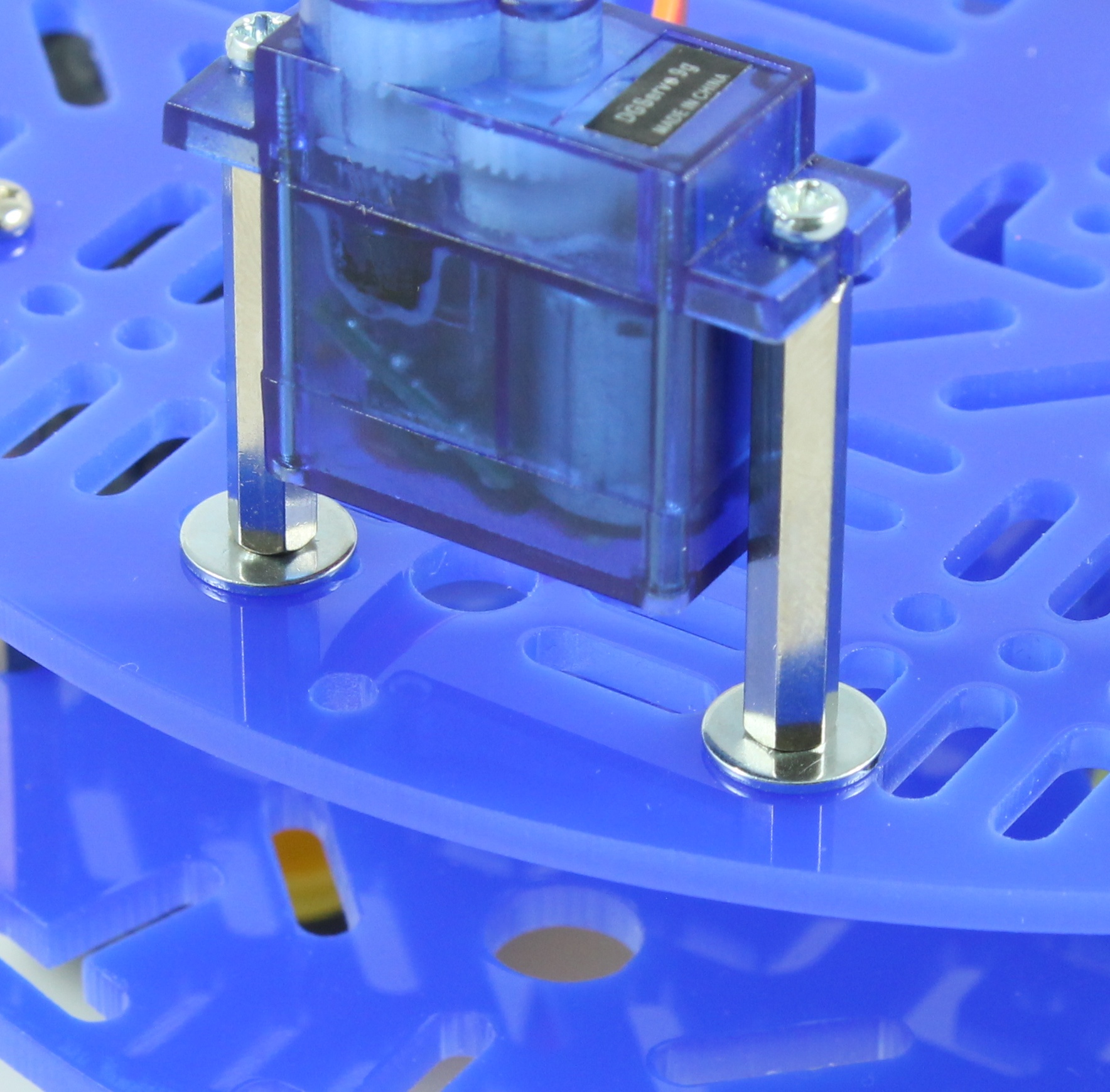
M2 hex spacers come with washers to attach to the 2WD chassis

Use washers as shown
Mount the Pi on the chassis using the Raspberry Pi Fixing Kit. The picture below shows the best position we found for the spacers. This gets the Pi close enough to the Pan/Tilt neck so that the standard 15cm Pi camera cable can be used to attach the camera. Tip: only the position of the bottom left and top right spacers are critical, the other 2 spacers are just there to support the Pi.
Update: If you have a Model B+ Pi, or a Raspberry Pi 2 see the section on attaching the Model B+ and Pi 2 below.
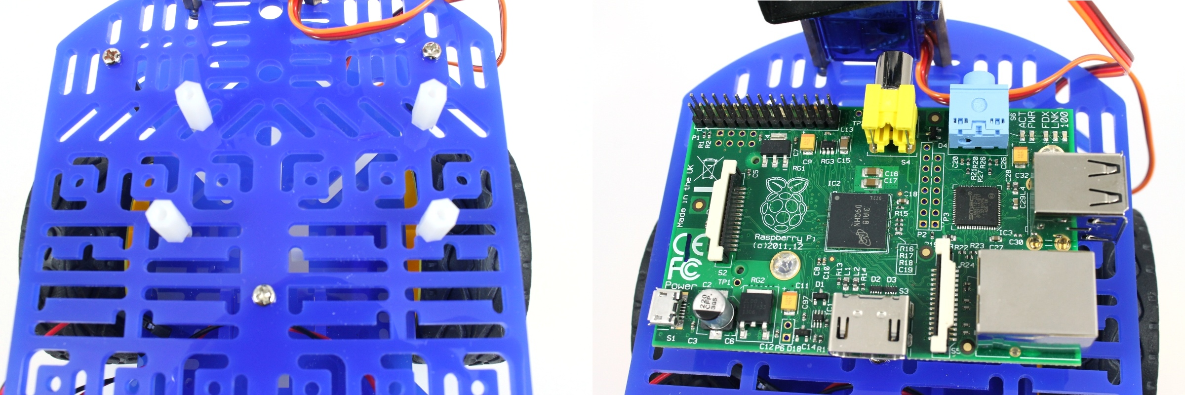
Attach the Pi to the 2WD chassis
Mount the Mini Driver Board on the chassis using the spacers it comes with. We mounted ours to leave space for an optional breadboard in the future, but this means that we weren’t able to get screws into all of the mounting holes on the Mini Driver. Still, 2 or 3 screws is all it needs for stability.
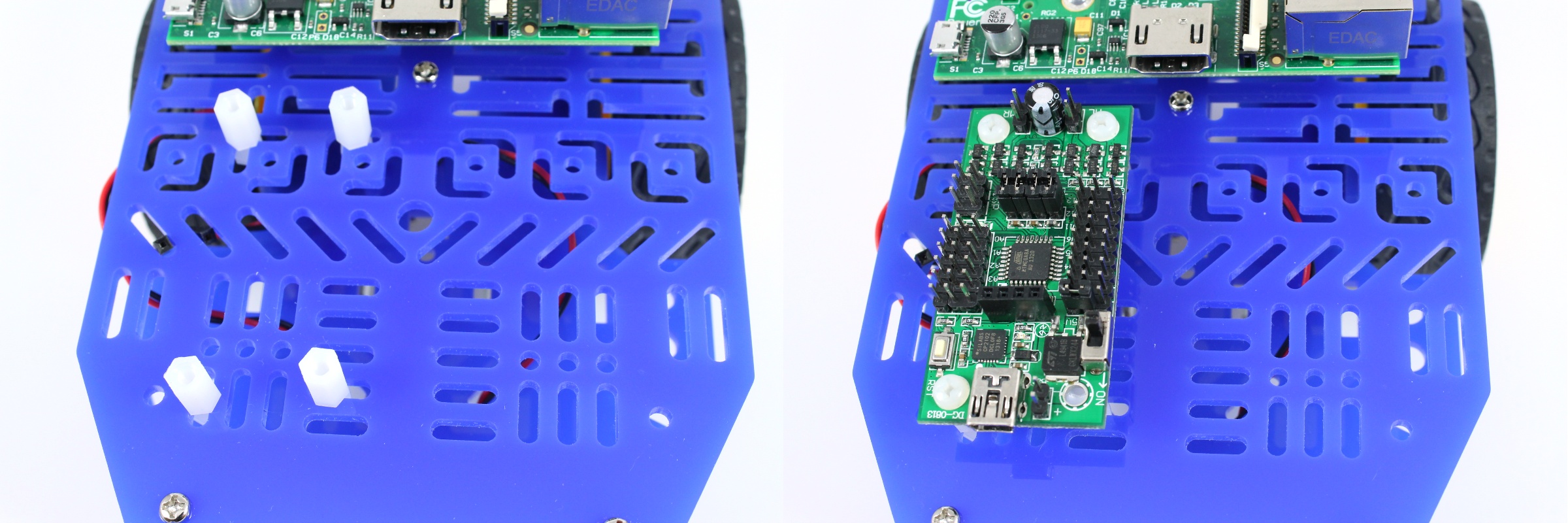
Attach the Mini Driver to the 2WD chassis
Connect the Pi to the Mini Driver board using a USB cable. The shorter the cable you can use here the better. We used the 1m USB cable that we stock and so wrapped it round the Pi 3 times to keep things neat.
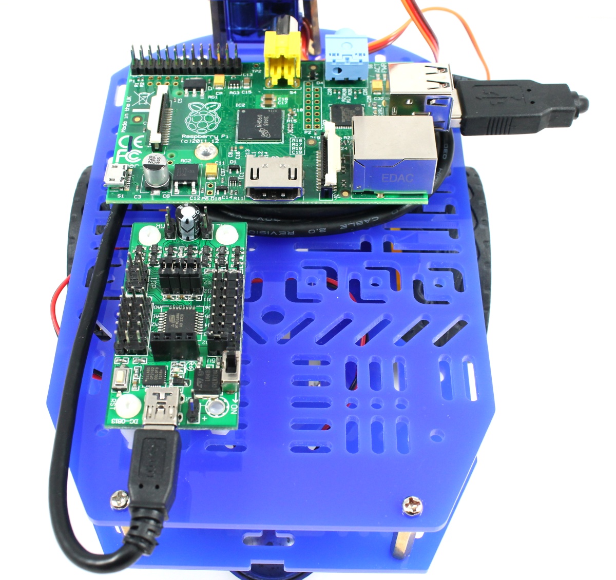
Connect the Pi to the Mini Driver using a USB Cable
Attaching a Model B+ or Raspberry Pi 2
The Raspberry Pi Model B+ and the new Raspberry Pi 2 are both a great fit for this robot kit as they use less power than the old Model B Pi, and contain an extra 2 USB ports, and in the case of the Pi 2, you get more computing power. To attach them to the chassis we recommend positioning the Raspberry Pi Fixing Kit spacers and the Mini Driver as shown below. We moved the Mini Driver over to the right as this allows a HDMI monitor to be attached if required for debugging purposes.

Attaching the Model B+ Pi or Pi 2 to the Chassis
Now attach the camera to the Pan/Tilt kit using the sensor fixing kit. Once the camera is secure, use the camera cable to connect the camera to the Pi. The cable attaches to the Pi using the connector closest to the network port, with the reinforcing strip facing the network port and the exposed pins facing away from the network port. The connector is used by raising up the top part of the connector to loosen it, inserting the cable and then pushing the top part of the connector down to hold the cable in place. The cable attaches to the camera with the exposed pins facing forward. Note: When threading the cable through the pan/tilt unit, please be very careful not to let it snag.
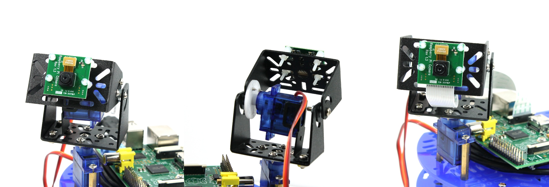
Attach the camera to the Pan/Tilt neck
Now connect the wheel motors and the neck servo motors to the Mini Driver as shown in the diagram below. The exact order of the red and black wires for the wheel motors is not important as if you get it wrong they will just turn in the wrong direction. This can be fixed by just swapping them over when you notice it.
On the pan/tilt servos, the red (middle) wire is Vcc, the brown wire is Ground and the orange wire is the signal wire. Attach the pan servo to the row marked D11, and the tilt servo to the row marked D6.
Please Note: The servo motors used to be attached to pins D3 and D4, but had to be moved to allow for the possibility of attaching encoders.
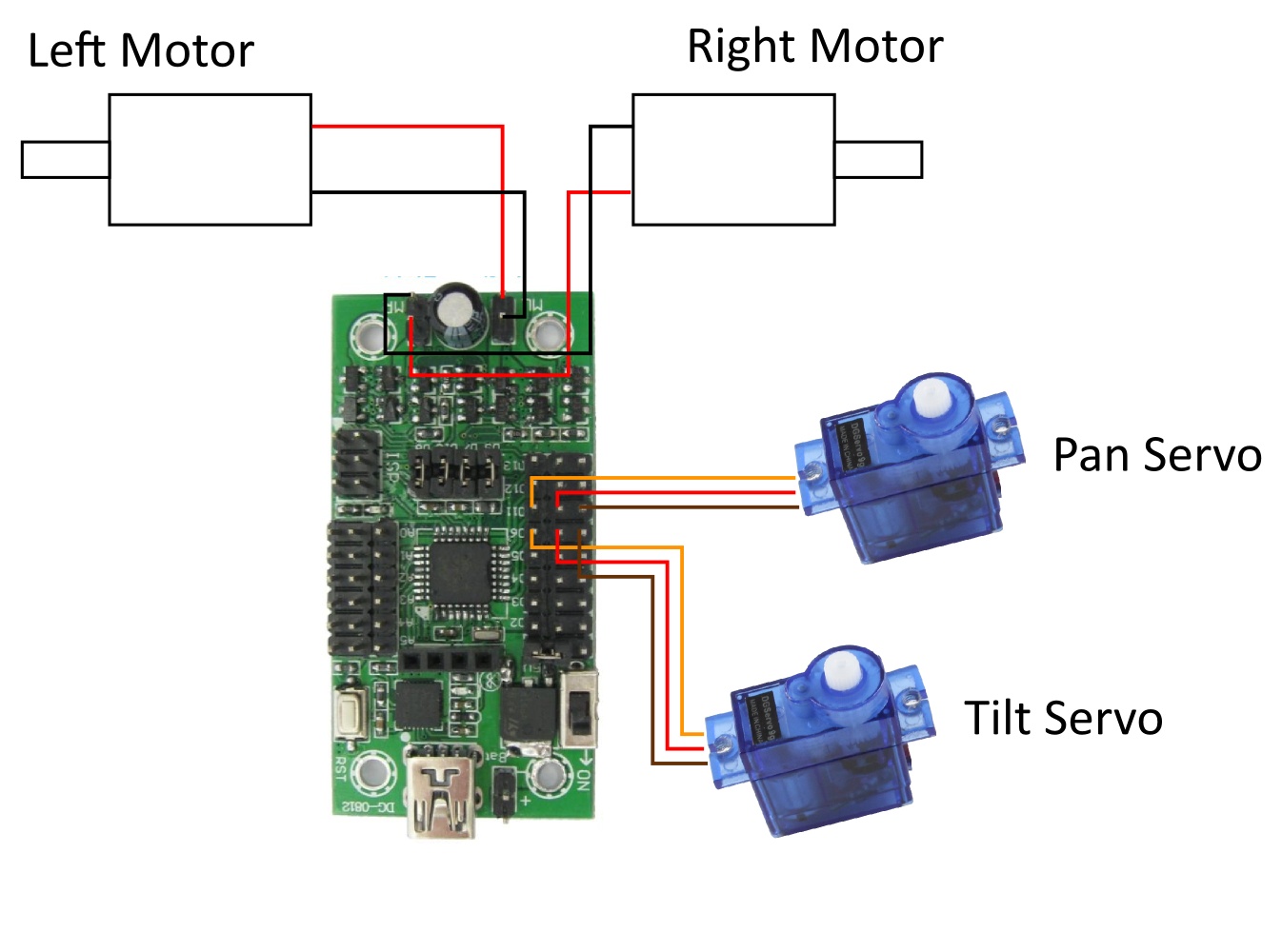
Attach the wheel motors and the neck servo motors to the Mini Driver.
WiFi
Plug your USB WiFi dongle into the Pi. We highly recommend using the Edimax EW-7811Un WiFi dongle as it seems to consume less power than other Wifi dongles, and the software we provide works really well with the Edimax EW-7811Un. Other WiFi dongles may work however.
Powering the Robot
To power the robot, you can either use 6xAA batteries, or you can use a USB powerbank.
Running the Robot from 6xAA Batteries
To get as much life as possible out of the batteries, we use a device called a UBEC (Universal Battery Elimination Circuit). This is an efficient switching voltage regulator which means that less of the battery pack’s power is wasted as heat as its high voltage is converted to 5V for the Pi.
First connect the UBEC to the Mini Driver. This is done by connecting the red input wire of the UBEC to the pin directly next to the on/off switch of the Mini Driver (this is connected to battery voltage), and then by connecting the black input wire of the UBEC to a GND pin on the Mini Driver. We’ve used the GND pin on the 3×2 programming header as this is unlikely to be used for anything else. Finally, plug the USB connector of the UBEC into the Pi.
Please Note: If you are planning to use a USB powerbank to power the Pi and mini driver, then you do not need to attach the UBEC to the robot. Instead, refer to the next section for instructions on how to attach the powerbank.

Connect the UBEC to the Mini Driver and the Pi
Now make sure that the Mini Driver switch is set to off, and attach a set of 6xAA batteries to the +/- pins of the Mini Driver. It’s important to use the 6xAA battery holder, rather than the 4xAA battery holder that comes with the robot, as 4xAA batteries just aren’t enough to power everything. Also, whilst you can just about get by with non-rechargeable (Alkaline) batteries we recommend that you use 6 good rechargeable (NiMh) batteries as these can provide more current for running the Pi and motors, and will give you much better battery life.
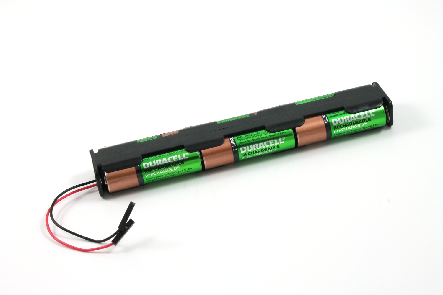
Rechargeable batteries such as these Duracell 2400mAh NiMh batteries are great for powering the robot
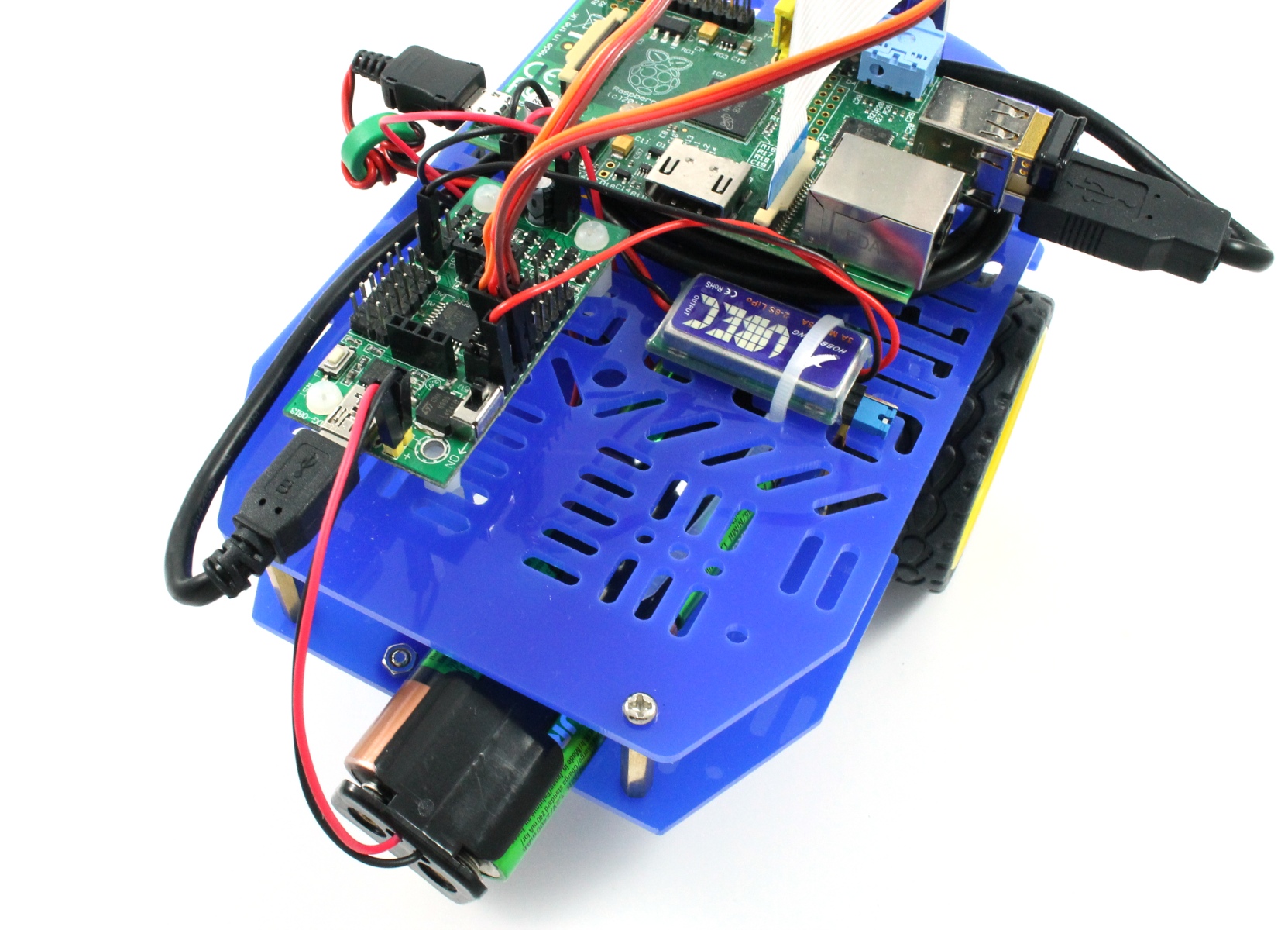
The robot with UBEC and 6xAA batteries attached
Running the Robot from a USB Powerbank
As an alternative to running the robot from 6xAA We now also offer a USB powerbank which can be used to run the entire robot (AA batteries not needed), and gives even better battery life (over 5 hours compared to approximately 3 hours). You can find details of this option, and how to connect it to the robot here.
Preparing the Software for the Robot
If you get to this part of the tutorial then congratulations, the hardware of your robot is now complete! ![]() Now, setting up the software for this robot from scratch can be a little involved so we’ve created an SD card image, with Raspbian and all the necessary software installed, that you can download here (get the latest version). Instructions for copying the image to an SD card can be found here. Please Note: If you choose this option, please remember to expand the filesystem after installation by running
Now, setting up the software for this robot from scratch can be a little involved so we’ve created an SD card image, with Raspbian and all the necessary software installed, that you can download here (get the latest version). Instructions for copying the image to an SD card can be found here. Please Note: If you choose this option, please remember to expand the filesystem after installation by running
sudo raspi-config
and choose the ‘Expand Filesystem’ option.
If you lack the confidence to copy the image to an SD card then you can buy a pre-installed SD card from us here. Alternatively you can see all of the steps we went through to set up the image on our main site here. All of the software we wrote for this robot is open source and can be found in this repository.
Whichever route you choose to go down, once you have your SD card, plug it into the Pi.
Powering up and Driving the Robot
Power on the robot using the switch on the Mini Driver, and give the robot 2 to 3 minutes to power on and settle down. The first time you power the robot on, it needs to download a sketch to the Mini Driver and so will take a bit longer to start up than normal. For those of you that know that the Mini Driver is really an Arduino – don’t worry – you don’t need to program it first, that’s done automagically by the wonderful library Ino.
The Raspberry Pi is configured to act as a WiFi access point, so connect to the new wireless network that should appear called ‘Pi_Mini_Robot’. The password for the network is ‘Raspberry’.
Note: Very occasionally the WiFi dongle on the Pi won’t get an IP address (known bug) and so you won’t be able to connect to the network (your device will spend ages authenticating and getting an ip address). This problem is usually resolved by turning the robot off and on again.
The robot is controlled with a web interface which means it should hopefully be accessible from the widest range of devices possible. The web interface does use HTML5 however, so you’ll need to use an up to date browser. We found that Chrome works well on all the platforms we’ve tested it on.
To control the robot type the IP address 192.168.42.1 into the address bar.
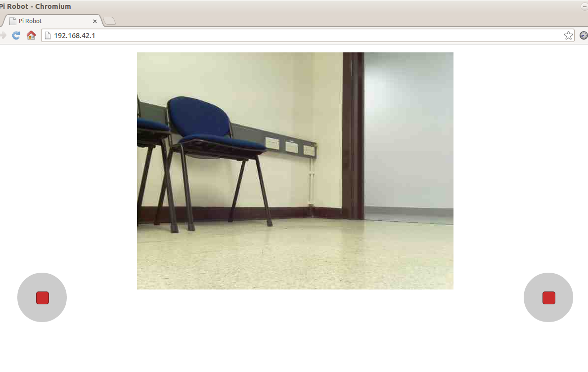
Drive the robot with the left joystick, and look around with the right joystick
The interface screen should consist of the view from the robot’s camera, and 2 joysticks (not nipples). The left joystick controls the robot’s wheels, the right joystick controls the robot neck. Tap on the right joystick to return the neck to its starting position.
Adjusting the Range of Motion of the Pan/Tilt Servos
Depending upon how accurately you were able to assemble the servo motors of the neck, you may find that setting both servos to 90 degrees does not centre the head. In some cases you may need to partially disassemble the pan/tilt head to correct this, but you may also be able to get away with adjusting the PWM pulse widths that correspond with 0 and 180 degrees. Access the configuration page at 192.168.42.1/config.html. The sliders let you move the pan and tilt servos around, send modified PWM values to the robot by pressing the save button.
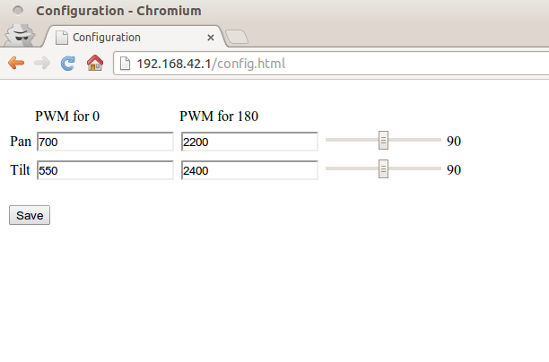
The robot configuration screen
Troubleshooting
We’ve tried to make everything as straightforward as possible in this tutorial, but there are still a number of things that can go wrong. If you have any questions or problems, please post in our forums, or leave a comment below.
Software Outline
This blog post has already turned into a bit of an epic, so we’ll leave a full discussion of the robot’s software to another day. The important points are, it’s open source ad can be found in this repository here. ![]() We’d like to develop it further and adapt it to other Raspberry Pi robot so any comments, suggestions, or bug fixes are very much appreciated. Also, we’re happy to offer pointers if you’d like to use it for your own Raspberry Pi robot.
We’d like to develop it further and adapt it to other Raspberry Pi robot so any comments, suggestions, or bug fixes are very much appreciated. Also, we’re happy to offer pointers if you’d like to use it for your own Raspberry Pi robot.
Update: Programming the Robot
We’ve now released a Python library that lets you write control scripts to make your robot autonomous, and to process images from its camera using OpenCV. You can find details of the library in this blog post.
Update: Adding Sensors to the Robot
We’ve updated the robot’s software so that it’s really easy to add sensors to the robot for use in your robot control scripts. Find out more in this blog post.
Taking things Further
The power of the Raspberry Pi gives a huge amount of flexibility for expanding on this tutorial and taking things further. A robot with a camera can use computer vision to recognise objects, and people, or to recognise locations in order to build a map of it’s environment. Some processing can be done on the robot, but the WiFi connection means that processing can also be done on another more powerful computer.
The robot can also be expanded with more sensors and servo motors, connected either to the Pi or to the Mini Driver board. The software can also be adapted fairly easily to work with other robots.
Have fun exploring. ![]()
Alan,
Here are a few comments on the robot hardware, which I’ve successfully built:-
Magician Chassis:
Because of the change from an omni wheel to a caster, the printed parts list doesn’t match what is required. However, there are sufficient extra screws to build it.
Dagu Pan / Tilt Kit:
1) The small self-tapping pan-head screws are extremely fragile and it is easy to strip the heads off. However, again, there are sufficient extras.
2) I suggest that if the holes in the motor that are are used to fix the spacers to mount on the chassis need to be reamed (I used long-nosed pliers), then this should be done – and the spacers attached – before the mechanism is assembled. Not having done so, I had to partially dis-assemble the kit to complete the process.
I may have some comments on the software later, when I’ve found my way around it!
Regards,
Alan Jardine.
Hi Alan,
Thanks for your comments. The caster is a recent change by Dagu, which is meant to be an enhancement, although I need to use it for a bit longer to be certain, hopefully they’ll also update the parts list soon to avoid confusion.
The Pan/Tilt can also be a bit fiddly, but that’s good advice on the mounting holes. I’m trying to get hold of some M2 spacers and screws which should hopefully provide a good alternative to having to enlarge the holes on the pan servo.
Looking forward to your comments on the software. Any issues getting it working, please let me know.
Regards
Alan
Some comments on the software:
Before downloading the image and writing it to a blank SD card, I thought I’d go through the instructions for creating the software (for learning purposes) and ran into the following problems:
1) Attempts to build the MJPG streamer failed at Step 1 on Miguel Grinberg’s blog at http://blog.miguelgrinberg.com/post/how-to-build-and-run-mjpg-streamer-on-the-raspberry-pi
because libjpeg8-dev imagemagick libv4l-dev could not be found. Noticing that the last updates to the blog were 4 months ago, I tried …libv42-dev, …43-dev and so on, to no avail.
2) The instructions on Bitbucket fail on the first step under “running” – sudo ./robot_web_server.py – because robot_web_server.py could not be found. (I’ve just noticed that the Bitbucket instructions differ from those on the blog at http://blog.dawnrobotics.co.uk/2014/01/creating-a-dawn-robotics-sd-card/ ,
but I’ve not been able to try the latter.)
Alan J.
Hi Alan,
Sorry for the delayed reply. Lots of possibilities for things to go wrong with following those instructions. I think that it was the act of reading through them that made me decide to provide a complete SD card image.
First up, are you following this blog post and starting with the 2013-07-26-wheezy-raspbian image? Or have you tried a more up to date one or different distribution? If you are using the 2013-07 image, then have you run a ‘sudo apt-get update’ before following Miguel’s tutorial? This would have been done in the Adafruit access point tutorial, but might have been skipped if you were trying things in a different order. I’m fairly confident that Miguel’s tutorial should work if you start from the same image as I did, but it would be good to work through any problems that may occur with a different image.
As for the bitbucket instructions, yeah they could be clearer, by inculding the cd command I assume. I’ve updated the instrctions on bitbucket to try to fix this.
Regards
Alan B – thought it best to add the surname initial to make it clear I’m not having a conversation with myself.
Hi!
Did You try to use the Raspberry Pi model A?
It should have less power consumption than model B.
Let me know!
I just want to buy Your kit is seems really nice.
Maybe it is not so mandatory the pan&tilt for the RPi camera, because the bot can move and rotate on its own.
Best regards,
Camillo
Hi Camillo,
Sorry for the delay in approving and replying to this comment. It got lost in amongst all the spam comments I get.
I haven’t tried using a Model A for this kit but it should work. The main problem would be that you couldn’t use USB to get the Pi to talk to the Mini Driver (without using a hub) as the single USB port of the model A would be needed for WiFi. This could be worked aroud by wiring the serial port lines from the Pi GPIO to the RX TX lines of the Mini Driver, and another GPIO pin to the Reset line of the Mini Driver. You’d need to do 3.3V to 5V level shifting though for at least one of the lines so it could get a little messy.
Also, yes you could do without the Pan/Tilt, but the idea is that you can look to the left and right more quickly and accurately with a pan mechanism, and of course the tilt mechanism is needed to look up or down.
Regards
Alan
I forgot a question; would it be possible to power the Dagu Mini Driver (and RPi as well) with a Phone Emergency Battery Charger instead of 6 AA batteries?
Thank you!
Hi Camillo,
If you mean a USB Power bank then yes that could be used to power the Pi and Mini Driver. It would need to be able to provide more than 1A to power the motors as well, although you could then just use the 4xAA battery holder in the 2WD Chassis kit to drive those.
Regards
Alan
Hello,
Great build, but I am having a little trouble once up and running.. T set up the wifi, no adapter is showing? I am sure I have sufficient power with a separate source for the Pi. I am using one of these: http://www.amazon.co.uk/dp/B005SBTZLQ/ref=pe_385721_37038051_TE_3p_dp_1
It has always worked before? A little new to this, so hope you can help!
Thanks,
Kerry
p.s
It works with my own SD cards, but not the preloaded one with the kit – if thats useful?
Hi Kerry,
Thanks for the question. I think that the problem is that the version of hostapd we use only works with a few WiFi adaptors. Steps to fix this are mentioned in this forum post, but I’ll recap them here for anyone interested.
Basically we followed this Adafruit tutorial to set up the Pi as an access point. To modify the setup to work with your adaptor you need to do the following
Change the line that reads driver=rtl871xdrv to say driver=nl80211 in /etc/hostapd/hostapd.conf
Run the following commands to remove Adafruit’s patched version of hostapd
sudo mv /usr/sbin/hostapd /usr/sbin/hostapd.ADAsudo mv /usr/sbin/hostapd.ORIG /usr/sbin/hostapd
Now, hopefully when you reboot your WiFi adaptor should be working and your Pi will be acting as an access point. If not then can you tell me the results of running ‘lsusb’ and ‘ifconfig wlan0′ please?
I’d like to automate the detection of WiFi dongles so that hostapd work with any of them, but I’m finding it difficult to find the time to do much coding at the moment.
Regards
Alan
Hi Alan,
Such a quick response – thank you!
I followed the instructions, all worked well but the adapter didn’t show on reboot.
lsusb shows:
Bus 001 Device 002: ID 0424:9512 Standard Microsystems corp
Bus 001 Device 001: ID 1d6b:0002 Linux foundation root hub
Bus 001 Device 003: ID 0424:ec00 Standard Microsystems corp
Bus 001 Device 006: ID 1a40:0101 Terminus technology inc. 4-port HUB
Bus 001 Device 005: ID 148f:5370 Ralink technology, Corp. RT5370 Wireless adapter
Bus 001 Device 008L ID 1c4f:0002 SiGma Micro keyboard TRACKR Gamma ivory
ifconfig wlan0 shows:
wlan0 Link encap:Ethernet Hwaddr 7c:dd:90:54:ed:60
UP BROADCAST RUNNING MULTICAST MTU:1500 Metric:1
RX packets:0 errors:0 dropped:0 overruns:0 frame:0
TX packets:0 errors:0 dropped:0 overruns:0 carrier:0
collisions:0 txqueuelen:1000
RX bytes:0 (0.0 B) TX bytes:0 (0.0 B)
Maybe I need to just get the right wifi? I could have done with it to show a class friday, but maybe express delivery will be available!
Kerry
Hi Kerry,
Sorry for the delay on this reply. I think that you’re almost there, I think that the problem now is just that your WiFi dongle may need more power on start up than the Edimax dongle.
To test this, can you power your Pi with a 5V adaptor and see if the WiFi works then? If it does, then you should be able to get your robot working by using a USB powerbank if you have one?
Regards
Alan
Hi Alan,
I brought the recommended Wifi to see if it would work, and I changes /etc/hostapd/hostapd.conf back to the first dongle- rtl871xdrv
Then I rebooted. Unfortunately still no adapter showing.
I have taken it all apart and changed the batteries too and still have a mains power for the pi.
Any ideas? Thanks
Kerry
Hi Kerry,
Using the recommended WiFi dongle with mains power should be pretty much rock solid.
A couple of things to try
* Can you try copying our SD card image to your SD card again? Just in case there were any extra changes you made to the SD card that haven’t been undone
* Try with just the WiFi dongle and mains power, nothing else. What do you get when you run ifconfig wlan0?
Regards
Alan
Hello,
I’ve a problem when execute:
sudo ./robot_web_server.py
At first, works fine, but when I move the head of the robot with the right joystick in the web server interface, the python sysout shows:
————————————————————————————————————————————————————————————————
SerialException: write failed: [Errno 5] Input/output error
Exception in callback
Traceback (most recent call last):
File “/usr/local/lib/python2.7/dist-packages/tornado/ioloop.py”, line 830, in _run
self.callback()
File “./robot_web_server.py”, line 264, in robotUpdate
robot.update()
File “/home/pi/sockjs-tornado/raspberry_pi_camera_bot/robot_controller.py”, line 189, in update
self.leftMotorSpeed, self.rightMotorSpeed, self.panAngle, self.tiltAngle )
File “/home/pi/sockjs-tornado/raspberry_pi_camera_bot/mini_driver.py”, line 384, in setOutputs
self.connection.setOutputs( leftMotorSpeed, rightMotorSpeed, panAngle, tiltAngle )
File “/home/pi/sockjs-tornado/raspberry_pi_camera_bot/mini_driver.py”, line 263, in setOutputs
self.serialPort.write( msgBuffer )
File “/usr/local/lib/python2.7/dist-packages/serial/serialposix.py”, line 518, in write
raise SerialException(‘write failed: %s’ % (v,))
SerialException: write failed: [Errno 5] Input/output error
……………………………..
……………………..
…….
————————————————————————————————————————————————————————————————
I’ve not problems with streamming. When this error appears, I make a reset to the pi. Antoher problem with robot is that I can’t move him with the left joystick.
When starts the python software, it seems works fine… but after minuts when I begin play with the interface appears the previous errors .
This is the sysout at begins:
———————————————————————————————————————————————–
DEBUG:tornado.general:sockjs.tornado will use json module
INFO:root:Starting web server…
INFO:tornado.access:200 GET /robot_control/info (15.195.185.79) 13.93ms
INFO:tornado.access:200 GET /robot_control/info (15.195.185.79) 12.85ms
INFO:tornado.access:200 GET /robot_control/info (15.195.185.79) 10.41ms
INFO:tornado.access:200 GET /robot_control/info (15.195.185.79) 9.65ms
INFO:tornado.access:200 GET /robot_control/info (15.195.185.79) 13.54ms
INFO:tornado.access:200 GET /robot_control/info (15.195.185.79) 9.72ms
INFO:tornado.access:200 GET /robot_control/info (15.195.185.79) 10.11ms
INFO:root:Read 0XACED 0.28
INFO:root:Expected 0XACED 0.28
INFO:tornado.access:200 GET / (15.195.185.79) 84.51ms
INFO:tornado.access:304 GET /js/jquery.js (15.195.185.79) 166.51ms
INFO:tornado.access:304 GET /js/jquery.joystick.js (15.195.185.79) 15.18ms
INFO:tornado.access:304 GET /js/sockjs-0.3.min.js (15.195.185.79) 17.87ms
INFO:tornado.access:200 GET /robot_control/info (15.195.185.79) 10.18ms
INFO:tornado.access:200 GET /robot_control/info (15.195.185.79) 10.20ms
INFO:tornado.access:204 POST /robot_control/262/barj7w46/xhr_send (15.195.185.79) 130.16ms
———————————————————————————————————————————————–
Can you help me please???
Best Regards
Hi Alberto,
Thanks for your question. The part of the log that says
INFO:root:Read 0XACED 0.28
INFO:root:Expected 0XACED 0.28
shows that a connection was made to the Mini Driver, but it then seems to be flaking out after a while.
How are you powering your robot? Power issues can cause a lot of problems, so it might be worth powering your robot with a wall adapter for a bit just while you debug things.
Regards
Alan
Hi Alan,
I’m powering the robot with wall adapter to he pi. I disconnected the power wires of the Dagu Mini Driver to the 6xAA battery pack to avoid unnecessarily draining the battery.
Is it wrong? Powering the robot from 6xAA directly?
Thanks for help me.
Regards,
Alberto
Hi Alan,
I’m powering the robot with 6xAA battery and works fine during a few seconds (about 1 minute ) and then crashes. Sysout python shows a similar error.
When Robot crashes I need restart the raspberry. In another cases if I rerun the robot_web_server.py , the connection is not made to the Mini Driver and I need restart all.
——————————————————————————————————————————————————
SerialException: write failed: [Errno 5] Input/output error
ERROR:tornado.application:Exception in callback
Traceback (most recent call last):
File “/usr/local/lib/python2.7/dist-packages/tornado/ioloop.py”, line 830, in _run
self.callback()
File “./robot_web_server.py”, line 264, in robotUpdate
robot.update()
File “/home/pi/sockjs-tornado/raspberry_pi_camera_bot/robot_controller.py”, line 189, in update
self.leftMotorSpeed, self.rightMotorSpeed, self.panAngle, self.tiltAngle )
File “/home/pi/sockjs-tornado/raspberry_pi_camera_bot/mini_driver.py”, line 384, in setOutputs
self.connection.setOutputs( leftMotorSpeed, rightMotorSpeed, panAngle, tiltAngle )
File “/home/pi/sockjs-tornado/raspberry_pi_camera_bot/mini_driver.py”, line 263, in setOutputs
self.serialPort.write( msgBuffer )
File “/usr/local/lib/python2.7/dist-packages/serial/serialposix.py”, line 518, in write
raise SerialException(‘write failed: %s’ % (v,))
SerialException: write failed: [Errno 5] Input/output error
ERROR:tornado.application:Exception in callback
——————————————————————————————————————————————————
Any help?
Sorry for my bad english
Regards,
Alberto.
Hi Alberto,
Your english is fantastic. What kind of AA batteries are you using? Are they rechargeable NiMh? And what capacity? 2400mAh?
More importantly, do you get the same error if running the Pi from the wall socket? You’ll need to keep the batteries connected to the Mini Driver to make the wheels move.
Regards
Alan
Hi Alan,
I’m not sure what is the model of AA batteries (NiMH or NiCd). I check the capacity and model when arrive at home, but I’m sure that are not rechargables.
The error is the same in both cases (running from the wall socket or from batteries):
——————————————————————————————————————-
SerialException: write failed: [Errno 5] Input/output error and the errors of lines ,
——————————————————————————————————————-
Only difference is that the robot works during a very short time with powering batteries until crashes.
While robot is running , the head moves fine, but the joysitck of wheels is very sensitive, is very difficult to move straight and the movements are circular.
Those are the main problems that I have.
Regards,
Alberto.
Hi Alberto,
I’m afraid that the robot won’t run very well at all on non-rechargeable (alkaline) batteries. These have a higher voltage than rechargeable batteries, but really struggle to provide the current needed.
If you run from a wall socket and unplug the wifi dongle (to reduce current usage) does the program still crash?
The crash that you’re seeing is consistent with the serial connection being lost between the Mini Driver and the Raspberry Pi. I can get the same error by pulling out the USB cable connecting the two. Therefore, it looks like it’s either a power issue (try the robot with 6 good rechargeable batteries) or perhaps a problem with the USB cable. Do you have a spare cable you could try?
Regards
Alan
Hi alan,
Sorry for not answering before.
These are the tests:
-I’ve change de usb calbe. The error is the same.
- I’ve unplugged dongle wifi and and I connected to Rj45 directlye. The error is the same.
-I’ve think that the problem are the batteries.
I want to buy this model:
http://www.amazon.es/AmazonBasics-recargables-precargadas-2000-mAh-1900-mAh/dp/B00CWNMV4G/ref=sr_1_1?s=electronics&ie=UTF8&qid=1395938510&sr=1-1&keywords=8AA+pilas+recargables&tag=s6010000202-21
The price is cheap and and the reviews are good! Do you know ?
Regards,
Alberto.
Hi Alberto,
I have no experience using those batteries, but I think that they should be ok. I’ve used 2400mAh Duracell batteries which I’ve found to be great. Your batteries have a lower capacity (so you’ll get less running time from your robot), but should hopefully be able to provide enoung current.
Please let me know how you get on.
Regards
Alan
Hi there,
this looks like a fantastic wee project to try but I have a few questions if you don’t mind.
-I know everything is solder-less but how easy is this project? (I’m a Complete Newbie)
-can you run the robot from a remote location, i.e. keeping an eye on the pooch from work?
-what is the average runtime from a full charge to the batteries?
Many thanks for your time,
Andy.
Hi Andy,
Thanks for the questions. I would say that with regards to ease of use, if you use the same WiFi dongle as us, use good rechargeable batteries, and start off with our SD card, then this project is very straightforward to put together, and within a couple of hours, you should have a robot that you can drive around with your tablet, phone, PC etc.
Now, having said that, I would say that this project is definitely aimed at the technical hobbyist, rather than a general consumer. If you just want a robot that you can drive around remotely and see through its camera, then I would recommend something like the Wowee Rovio robot (search on ebay) which comes fully assembled, and offers a much more polished experience. The advantage of this Raspberry Pi Camera Robot is that all of its software is open source, and it can easily be adapted and customised to your own requirements. You can add on extra sensors, or a speaker, or extend the software for your own robot application, i.e. by adding computer vision/face recognition etc. In essence, you’re only limited by your time and imagination.
The knowledge and skills that you will require to extend and adapt the robot, largely depends upon what you want to do with it. From a software point of view the operating system on the Pi is Raspbian (a form of Linux), the control code and web server on the Pi is written in Python, and the control code on the Mini Driver is written in C/C++. If you’ve got programming skills but no hardware experience, then this would be a good robot to start with. If you’re less confident with software then I would recommend starting with our Rover 5 robot kit which just uses a Seeeduino (Arduino compatible) to control it. A Raspberry Pi does make a robot more complicated (although it also offers a lot of power).
With that in mind, with the network setup that we provide for the robot (robot operates as a WiFi access point), you cannot currently use the robot remotely over the internet. But it is possible to set a Raspberry Pi up for remote access over the internet (there are lots of tutorials for this on the web) and once you’ve done this, our web interface should work over the internet. Although there’s no guarantee this would be secure from hackers.
With regards to battery life, it all depends on what batteries you use, and how much the robot uses its motors. As an example, in a test that we ran recently, we started with 6 fully charged Duracell 2400mAH NiMH AA batteries and wrote a test program for the robot to make it run its motors forwards, backwards, left, right and then pause for 4 seconds each, continuously in a loop. (The robot was off the floor for this test). We got the robot to stream camera images continuously, and periodically moved its head back and forth. Running this test, our robot was easily able to run for over 2 and a half hours.
Anyway, hope that helps. If you’ve got any more questions, please let me know.
Regards
Alan
Hi Alan,
Do you have a tutorial for this with a 4 wheel chasis? Would it be difficult to modify your instructions to make it work with the 4 wheel chasis? Thanks!
Hi Greg,
Sorry for the massively late reply to this question. I think that this should translate really easily to a 4WD chassis. Although I’ve not yet had the chance to try this myself. For our 4WD chassis, you should just need to wire the 2 left motors in parallel to ML and the 2 right motors in parallel to MR on the mini driver. The main problem would be that there is a possibility that driving 4 motors will cause the voltage for the Pi to drop too much. Therefore you might need to run the Pi off a separate USB battery pack for a 4WD robot to work.
Regards
Alan
Hi Alan,
I bought rechargeables batteries 2400mAh and the robot works fine, but in several times when the neck moves up until his vertical/horizontal limit, the raspberry not responding and I need restart it (few times)
Another issue is the movement of the robot: The left circular joystick is not very precise and the robot moves in circles. Is very difficult go straight on. Is there any solution for this?
Regards,
Alberto.
Hello,
Is it possible to configure the robot to connect to WIFI rather than making it its own network? I am basically trying to configure the robot to connect to my WIFI and be able to control it around my home from any location.
Hi there,
Sorry for the delay in replying to this question, my wordpress notifications don’t seem to be working that well. :/
The robot is just running standard Raspbian so you can edit the /etc/network/interfaces file to get any kind of network setup you want. If you google then there are quite a few tutorials out there on setting up WiFi for the Raspberry Pi, but let me know if you need more help.
Regards
Alan
Hi Alan,
I have 4wd and everything, but not smartphone, tablet.
Can I do that for obstacle avoidance? But i’m using python 3 and cannot work with pyserial. I will have to modified by myself to see if i can do manually without using tablet or smartphone.
Hi Supra,
If you don’t have a tablet or a smartphone then you can control the robot using a standard computer. For obstacle avoidance you can attach sensors such as the ultrasonic sensor we sell to the mini driver.
You should be able to use pyserial with Python 3. You just need to install the python3-serial package with apt-get.
Hope that helps, let me know if you need more detail on something.
Regards
Alan
Regards
Alan
Hi,
I did follow carefully all the instructions to build the robot. Congratulations for the professional job.
I do have a problem running the robot.The camera works fine but on the screen I just can see one bottom joystick on the left which is also unavailable. I tried Safari and Chrome browsers and I have same problem.I have powered the system with just a LIPO battery 7,4 Volts 1800 mAh. Is it correct? Do I have to power also the Raspberry with a 6V battery?
The above side I cannot run the robot ….Is that due to the unavailable buttons or also to pouring I have used?..
I will be very grateful if you can reply soon..
Thanks a lot for your help.
Arnaldo
Hi Arnaldo,
By the looks of it, your battery should be enough, although your problems sound a bit like a power issue (see the first message in this forum post). A good way to debug things initially is to start by running the Pi off a wall adapter and also by connecting to the web interface over a wired connection. Also, can you tell me the result of navigating to http://PI_ROBOT_IP_ADDRESS/logs.html on the Pi Robot.
Regards
Alan
Hi Alan, thanks a lot for your prompt reply. You are very kind. Here is the log you have required:Main Log
DEBUG:tornado.general:sockjs.tornado will use json module
INFO:root:Starting web server…
INFO:root:Read 0XACED 0.28
INFO:root:Expected 0XACED 0.28
INFO:tornado.access:200 GET /robot_control/info (192.168.1.4) 12.85ms
INFO:tornado.access:200 GET /logs.html (192.168.1.4) 152.52ms
INFO:tornado.access:304 GET /js/sockjs-0.3.min.js (192.168.1.4) 20.79ms
INFO:tornado.access:304 GET /js/jquery.js (192.168.1.4) 34.66ms
INFO:root:SockJS connection closed
INFO:root:SockJS connection closed
INFO:root:SockJS connection closed
INFO:root:SockJS connection closed
INFO:root:SockJS connection closed
INFO:root:SockJS connection closed
INFO:root:SockJS connection closed
INFO:root:SockJS connection closed
INFO:tornado.access:200 GET /robot_control/info (192.168.1.4) 10.27ms
The battery I have used is the one I have told you: LIPO 7,4 1800 mah.
Now I can see the two buttons but still they do not work!
I’m noticing that the motor driver is a quit warm under the micro USB close to the power pins…
Waiting for your kind comments…
Arnaldo
Hi Arnaldo,
The warmth on the mini driver comes from the voltage regulator, and is quite normal. The log shows that the mini driver firmware is starting up properly
INFO:root:Read 0XACED 0.28
INFO:root:Expected 0XACED 0.28
but for some reason the joystick commands aren’t getting through. Hmmm
If it is a power problem, then if you power the Pi from a wall adapter at the same time then that may solve the problem for the neck servos at least. Can you try this and let me know what happens?
The joysticks may not work immediately when you connect to the Pi, as there is a short delay, whilst the Pi connects to the Mini Driver. The neck servos (controlled from right joystick) shouldn’t require lots of current so should be working now even with power problems. Can you check
– do the neck servos centre themselves and resist movement after the Pi connects to the mini driver?
– are the servo motors connected properly? (sorry, just to check everything)
Regards
Alan
Hi Alan,
I did what you suggested and it works fine…the strange is that I had already done the same thing but unsuccessfully..very very strange…the robot has recognized yiur authority
So what do you think should be the correct powering without the wall connector and leaving the Lipo battery I already have?
The last….
Screen resolution ..
Both on the Ipad , safari, and on Mac with safari or chrome, the two buttons are very far one from another so the do not appear on the screen both…just using the full screen mode…
It is not a big issue..but I thin that can be solved..
Thanks reallly very much for your patience and kindness.
Best Regards.
Arnaldo
Hi Arnaldo,
It looks like the battery you have on its own just can’t provide enough power for both the motors and the Raspberry Pi. Which is slightly surprising, as I would have thought a LiPo battery would be fine (although I haven’t directly used LiPo cells myself just USB powerbanks). I would suggest to perhaps try powering the Pi with a small USB powerbank to give the LiPo battery some extra help. Also maybe check to see if there’s any difference when the battery is fully charged?
For the web interace issues, if you don’t mind modifying a bit of HTML then you can change the web interface in the /home/pi/raspberry_pi_camera_bot/www directory. If you look at index.html, then you should see that the position of the 2 joysticks is set in the function layoutControls.
Regards
Alan
Hi! It would be nice to have a self charging station for the bot.
May be using wireless induction? Is it possible?
And is it also possible to put the Raspberry into stand by mode (to lower the battery consumption) until a sensor detects something (like a PIR or audio detected)?
Camillo
Hi Camillo,
Those are both great suggestions, and I’d definitely like to get wireless charging working at some point, although I think that it will require some specialised hardware to support it.
I’m not aware of a standby mode on the Pi, so what you’d need to do there, is use something like a relay so that the mini driver could control the power that’s sent to the Pi. You could then have sensor on the mini driver wake the Pi up.
Regards
Alan
Hi Alan, Thank you for the answers!
I think switching on & off the RPi can corrupt the file system and is a little bit slow.
I saw that the BeagleBone Black board has a chip that can go into deep sleep:
http://e2e.ti.com/support/arm/sitara_arm/f/791/t/331883.aspx?pi301021=2
But I did not try it.
Apart from the camera which is very well developed for Raspberry Pi, do You think a BeagleBone Black could completely replace both the RPi and the Dagu Mini Driver in this robot?
Hi Camillo,
I haven’t tried the Beaglebone Black myself, but it looks like it could be a good alternative to the Raspberry Pi. I chose the Raspberry Pi for this robot because of the camera, and also because they seem to be more popular here in the UK (although that could just be the people I hang out with ). If you did use the Beaglebone Black instead of the Raspberry Pi then you would still need the Mini Driver, as as far as I know, the Beaglebone Black doesn’t have motor drivers.
Regards
Alan
Hi Alan,
I bought rechargeables batteries 2400mAh and the robot works fine, but in several times when the neck moves up until his vertical/horizontal limit, the raspberry not responding and I need restart it (few times)
Another issue is the movement of the robot: The left circular joystick is not very precise and the robot moves in circles. Is very difficult go straight on. Is there any solution for this?
Regards,
Alberto.
Hi Alberto,
I think that what you’re seeing with the neck is that the servo motor is stalling (due to the pan/tilt being stiff). This causes too much current to be drawn, the voltage drops and the Pi will reboot. I haven’t had this problem with NiMh before, but if it keeps happening for you I would suggest maybe loosening up the bolts that join the brackets together.
The issue with the robot being hard to drive in a straight line is because the DC motors may go at different speeds (even with the same voltage applied) due to variations when manufactured. Usually this problem can be alleviated by scaling the speed of one of the motors so that it runs faster or slower. You can fix this yourself by looking near line 150 of robot_web_server.py. Basically if the left motor runs faster than the right one (robot turns right) you can multiply leftMotorSpeed by something like 0.9 to reduce it. If you don’t feel confident doing this then keep an eye on the blog because new software is coming this week for the robot (promised for last week, but stuff happened) that will let you alter this on the config page.
Regards
Alan
hi, i bought a new dagu mini driver, but its getting heated very soon when i power it using usb cable through laptop. what is the problem? also i want to use pwm on geared motors on pins 9 and 10. but since i am using servos also, the servo library doesnt permit this. so how can i use pwm? please help…
pramod
Hi Pramod,
Sorry for the delayed reply.
Are you only powering the board through USB? Or do you have a battery pack attached as well? The voltage regulator (and then the switch next to it) do get a bit hot, but in general, as long as it’s not extreme, this is nothing to worry about. It’s just one of the downsides of using a linear regulator. A switching regulator would be more efficient and produce less heat, but would have added a lot to the cost of the board.
If you’re using the Servo library then you need to set up a timer with an interrupt, and ‘bit-bang’ out a PWM signal for the motors. The firmware that I’ve used for this robot takes this approach and you can find it here.
Hope that helps, let me know if you need clarification on anything.
Regards
Alan
hi, the heating is in switch, voltage regulator and the usb slot.
pramod
I have weird behaviour to report… I tried the robot out with a different wireless stick (will get the Edimax soon). Obviously, it didn’t work. So then I plugged the card into another RPi which is hooked up to a TV. It started booting normally, then hostapd failed to load, and when it got to starting dhcpd, the screen just went blank. Not sure if the RPi was still working or it crashed completely… Is this normal? How can I connect to the RPi to change the configuration? Is sshd enabled on the image?
I should also mention that
1) the RPi was plugged into a mains power supply (the Adafruit 5.25V one, at that)
2) I wrote out the image to my own SD card (tried twice, same result)
Hi Peter,
Sorry for the delayed reply. The image does have sshd running on it. If you connect the ethernet port to a router it should get an IP address by DHCP and you can log in.
How are you connecting your TV to the Pi. The Pi should be outputting on HDMI. Things might not work if you were using the yellow jack instead? Is there, anything else plugged into the Pi?
Also, which WiFi dongle are you using, and what does it say when you run ‘lsusb’ with it plugged in? The new image should work with more dongles and perhaps I can update it further to get it working with yours.
Let me know how you get on with ssh.
Regards
Alan
Hi Alan,
Okay, I managed to connect, I’m not sure why I didn’t succeed before.
Yes, I’m using HDMI to connect to the TV. And the TV goes blank before I could log on locally. (???) Two fishy lines in the bootup messages: a WARN about insufficient space on rootfs, and a FAIL on starting hostapd.
The SD card I copied the image on is 16G, and df -h shows:
Filesystem      Size  Used Avail Use% Mounted on

rootfs          2.6G  2.5G     0 100% /

/dev/root       2.6G  2.5G     0 100% /

devtmpfs        180M     0  180M   0% /dev

tmpfs            38M  264K   38M   1% /run

tmpfs           5.0M     0  5.0M   0% /run/lock

tmpfs            75M     0   75M   0% /run/shm

/dev/mmcblk0p1   56M   19M   38M  34% /boot

tmpfs            75M  4.0K   75M   1% /tmp
I won’t bother with lsusb, because the wlan card seems to be working OK, after all:
wlan0     Link encap:Ethernet  HWaddr c8:60:00:5e:2f:a4

          inet addr:192.168.42.1  Bcast:192.168.42.255  Mask:255.255.255.0

          UP BROADCAST MULTICAST  MTU:1500  Metric:1

          RX packets:0 errors:0 dropped:0 overruns:0 frame:0

          TX packets:0 errors:0 dropped:0 overruns:0 carrier:0

          collisions:0 txqueuelen:1000

          RX bytes:0 (0.0 B)  TX bytes:0 (0.0 B)
Manually starting hostapd does not work either:
[FAIL] Starting advanced IEEE 802.11 management: hostapd failed!
Any ideas?
Hi Peter,
I think that the fail with hostapd is because of the WiFi dongles not being one of the type it recognises. The version of hostapd on the image should work with dongles that give one of the following when you run lsusb
7392:7811 Edimax Technology Co., Ltd EW-7811Un 802.11n Wireless Adapter [Realtek RTL8188CUS] # The Edimax is the most reliable
or
148f:5370 Ralink Technology, Corp. RT5370 Wireless Adapter # This is a very common cheap adapter used in a lot of dongles
Does lsusb give one of those, or a different one for you?
Also, looking at your disk free I notice an omission from my SD card flashing instructions. You need to run ‘sudo raspi-config’ and expand the disk image to get more than 100MB of space.
Regards
Alan
Hi Alan,
Okay, resizing the fs helped with the screen problem, now it boots into X without a problem.
Here’s lsusb:
Bus 001 Device 004: ID 0b05:1786 ASUSTek Computer, Inc. USB-N10 802.11n Network Adapter [Realtek RTL8188SU]
An Asus stick. It looks like (almost?) the same chipset as the Edimax. I guess that’s supposed to be good, but then why does hostapd fail?
Hi Peter,
It’s probably not good I’m afraid. My understanding (which is hazy) is that there is a linux WiFi driver called nl80211 which is compatible with quite a lot of WiFi dongles, and with hostapd. The EW-7811Un (Realtek RTL8188CUS) is not compatible with this driver, but Realtek due provide a modified version of hostapd which will work with it. I have basically used the version released by Realtek and compiled a version of hostapd which should work with both types of WiFi dongle.
The driver which hostapd should use is set in /etc/hostapd/hostapd.conf. You can edit it by running
sudo nano /etc/hostapd/hostapd.conf
Now, in my modified version of hostapd, the line driver=auto in hostapd.conf tells hostapd to try to guess which driver to use. You may be able to get hostapd to work with your wifi dongle by changing the line to driver=rtl871xdrv.
Please let me know how you get on. If that works, then I can edit my version of hostapd to be slightly more discerning…
Also, at some point I belive that the Realtek wifi dongles will be supported by the nl80211. This may already be the case in Linux kernels that are more up to date than the Raspberry Pis. At that point I can delete my hacked together version of hostapd, and just use the one from the repositorys.
Regards
Alan
No good, unfortunately I tried changing the driver line in hostapd.conf to
driver=r8712u
(I assumed I need the driver kernel module name here) – still fails.
Oh well. I am getting that Edimax stick this week, I just thought I’d give my current wifi adapter a try.
Thanks for the help, Alan!
Bad luck, this post has a bit more info in the comments if you search for r8712u, but nothing that looks like it would make it work.
Whilst you wait for the Edimax, you can access the web interface over ethernet if you want by navigating to the Pi’s IP address in a browser such as Chrome or Firefox.
Regards
Alan
thanx alan:) earlier we were powering through usb and also external battery. now we are downloading the code in the board and then using only external power. so its working fine:)
Hi,
I have managed to follow the instructions and have built my robot. Everything is working well except for one small problem mentioned by one of the previous posters: The robot will not hold a straight line when forward movement is selected from the web page. I’ve looked at robot_web_server.py but I have no idea how to add the multiplier suggested previously. Would it be possible to have more detailed instructions or a link to the modified software that addresses this also mentioned above.
Best regards,
Chris
Hi Chris,
If you’ve got the latest version of our software, then on the config page (192.168.42.1/config.html) you should find that there’s a motor tab that lets you set this multiplier with a slider. There’s also a ‘Drive Straight’ button which tries to drive forward and backwards to test the multiplier.
Hope that helps, let me know how you get on.
Regards
Alan
@Alan: some progress here. The Edimax stick has arrived and is recognised, the interface is brought up.
Problem #1: can’t connect over wifi. Both my computer (64bit Win7) and my wife’s (32bit Win7) says after entering the passphrase (Raspberry) that Windows is unable to connect. Yeah, informative… Oh, plus my Android phone ditto – it tries, then switches over to a working network.
Problem #2: connection over eth0 works BUT I can’t see the pan/tilt control joystick in the latest chrome or the latest firefox or IE11 (and believe me, I was pretty desperate to even try that). In Opera 12.64, the two joysticks are there, but the image doesn’t update unless I hit refresh on the browser.
Any ideas?
Hi Peter,
I’ve seen problem 1 when people enter the passphrase as raspberry (lower case r) but you’ve spelt it with a captial R so the doesn’t seem likely. Are you able to log into the Pi when it has this problem and run
sudo service hostapd status
sudo service isc-dhcp-server status
and let me know the ouput please?
Problem 2 seems very strange. Firefox doesn’t have to be that new (it works with version 20). Lets see if we can sort out problem 1 and I’ll give the absolute latest versions of Firefox and Chrome a go myself.
Regards
Alan
Both are running.
I have to run now, but I’ll try to do a clean install in the evening, although I don’t think I could have messed up that badly in tinkering. The hostapd.conf file does still have Raspberry as passphrase.
Done clean install of the 05/15 image. Rebooted my computer. Still can’t connect to wifi
Ok, this is really bizarre, it should literally be, SD card image, EW-7811UN, good power supply job done.
Some things to try
1. Can you send the output of running lsusb (to check your WiFi dongle is really a EW-7811UN)?
2. Can you send the output of running ‘ifconfig wlan0′?
3. Can you run ‘sudo nano /etc/hostapd/hostapd.conf’ and change the WiFi password to an all lowercase word of your choice? (Reboot for this to take effect)
4. Can you try the first (29/01) image?
5. What exactly does the Android phone say when tryig to connect? Does it spend ages trying to authenticate, or get an IP address? Or does it just immediately give up?
I’ll try to think of some more options.
Regards
Alan
Hi Peter,
After the things above, can you confirm that you can use your EW-7811UN as a normal WiFi dongle on the Raspberry Pi? Perhaps connecting to a router? If you can’t get it working as an access point you could at least use the robot with a larger WiFi network.
Regards
Alan
lsusb:
Bus 001 Device 002: ID 0424:9514 Standard Microsystems Corp.

Bus 001 Device 001: ID 1d6b:0002 Linux Foundation 2.0 root hub

Bus 001 Device 003: ID 0424:ec00 Standard Microsystems Corp.

Bus 001 Device 004: ID 7392:7811 Edimax Technology Co., Ltd EW-7811Un 802.11n Wireless Adapter [Realtek RTL8188CUS]

Bus 001 Device 005: ID 040b:2013 Weltrend Semiconductor
wlan0     Link encap:Ethernet  HWaddr 80:1f:02:ee:0c:84

          inet addr:192.168.42.1  Bcast:192.168.42.255  Mask:255.255.255.0

          UP BROADCAST RUNNING MULTICAST  MTU:1500  Metric:1

          RX packets:1 errors:0 dropped:0 overruns:0 frame:0

          TX packets:0 errors:0 dropped:0 overruns:0 carrier:0

          collisions:0 txqueuelen:1000

          RX bytes:0 (0.0 B)  TX bytes:0 (0.0 B)
Interestingly, I managed to connect with Android, about twice. But five minutes after succeeding once, I tried it again without changing anything, and it failed again. When it can’t connect, it gives up almost immediately, without getting to the ‘Obtaining the IP address’ message.
When it did happen, I could get the webpage with the builtin browser (I should say I still have Android 2.2), and the same problem: no second joystick. Something is probably awry at the Pi, because this phenomenon seems consistently cross-platform now.
Lowercase passphrase: no change. The passphrase is accepted – I don’t get the message saying incorrect passphrase, but the computer just gives it up as a lost cause immediately after.
I’ll get back to you once I tried the older image.
Hi Peter,
From lsusb it looks like you’ve got a bluetooth mouse or other bluetooth device attached to your Pi? (Bus 001 Device 005: ID 040b:2013 Weltrend Semiconductor). Can you please remove it and make sure that when trying to connect, only the SD card, EW-7811UN and power supply are connected to the Pi? The bluetooth mouse and WiFi dongle together might be drawing more power than your power supply can provide.
It’s unlikely that the default browser on Android 2.2 will be able to display the interface. Are you able to install Google Chrome on it please?
Inadequate power is often a problem when trying to use WiFi, so I’m hopeful that the bluetooth device is the key. Which power supply exactly are you using? You mentioned Adafruit I think, but how many amps can it provide?
Regards
Alan
Progress!
When I had the idea to try to connect to the robot using Lenovo Access Connections rather than Windows’ builtin wireless management tool – presto! it worked.
The fact that I changed the wireless channel to differ from my router’s also may have helped.
And the problem with Chrome seems to be PEBKAC: the browser wasn’t full screen and the joystick #2 was probably there all along, but outside the frame. Same goes for Android, probably: my phone has quite low resolution, and the page just doesn’t fit on the screen.
Now, I have the camera picture, the controls, but as of now they don’t work. They used to, so I’ll charge some batteries and probably figure it out by myself.
Thanks, Alan!
Fantastic. Glad you’re getting closer.
Okay, stumped with the new problem: the robot won’t move anything.
It boots, I can connect, I can see the live video, all the controls. The controls, however, don’t move any of the motors (servos included).
I unplugged everything but the driver board and the Edimax “stick”. (The bluetooth thing is a serial module – I would like that to work eventually, for easy programming when we are tired of just driving around, but for now it’s unplugged.) As of now, it’s powered by 6 NiMH Varta batteries and I measure a stable 4.96 V on the RPi.
The sliders on the config.html page don’t do anything either.
Any ideas? (Sorry for being such a difficult case…) Maybe try the new image again? (facepalm)
No worries, and hang on in there, I think we’re almost there.
I’d stick with the old image for now whilst we get it to work. But then I’d go back to the new image, (maybe do that now if you’ve got a spare SD card) as you’ll get much better video streaming.
When you turn the robot on, it may take a couple of minutes before the robot can move, as if the Mini Driver doesn’t have the correct firmware on it, the Pi needs to build and load it. Can you turn the robot on, wait about 2-3 minutes, connect to it and then send me the contents of 192.168.42.1/logs.html? Also, once you’ve done that, can you tell me if the neck servos turn freely when you try to move them, or do they resist movement? If it’s the latter then the Mini Driver will have been programmed.
Regards
Alan
Aha.
Excerpt:
...

WARNING:root:Got unrecognised response id - 4

INFO:root:Unable to connect to correct firmware, uploading...

INFO:root:No file copy needed

DEBUG:root:Building sketch in dir /root/.ino_uploader/mini_driver_firmware

DEBUG:root:Trying to upload /root/.ino_uploader/mini_driver_firmware/.build/atmega8/firmware.hex

DEBUG:root:uploadResult = 0

...

WARNING:root:Got unrecognised response id - 4

INFO:root:Read 0X0 0.0

WARNING:root:Got unrecognised response id - 4

WARNING:root:Got unrecognised response id - 4

WARNING:root:Got unrecognised response id - 4

INFO:tornado.access:304 GET / (192.168.42.14) 93.39ms

INFO:tornado.access:200 GET /robot_control/info (192.168.42.14) 9.29ms

WARNING:tornado.access:404 GET /favicon.ico (192.168.42.14) 8.50ms

INFO:tornado.access:200 GET /logs.html (192.168.42.14) 118.76ms

INFO:root:SockJS connection closed

INFO:tornado.access:200 GET /robot_control/info (192.168.42.14) 8.22ms

INFO:root:SockJS connection closed

INFO:tornado.access:200 GET /robot_control/info (192.168.42.14) 7.90ms

INFO:root:SockJS connection closed

INFO:tornado.access:200 GET /robot_control/info (192.168.42.14) 8.78ms

...
Ok, that’s not the best. It looks like the firmware upload is failing, although the fact that you’re getting the line ‘WARNING:root:Got unrecognised response id – 4′ means that something is coming back. This could be the voltage readings from the latest firmware…
Does a blue LED flash on the mini driver when you power it on, or when you press the reset (white) button on the mini driver? Trying it with the new image again, my be a good idea as it may have better luck uploading the firmware.
Regards
Alan
Okay, it works. Sort of…
The way I installed the motors (on both: wires are inside), it seems either the forward/back controls are swapped or the left/right, depending on how I connect them to the board. So some clarification on that in the tutorial would be great, because it was a pain to install them (lining up the through hole with the holes on the motor brackets and then getting the nut on in that confined space… I don’t want to do that again.) Also maybe an option to reverse left/right or forward/backward on the controller?)
That fact, coupled with the nonlinear answer of the motors to the controller (move it slightly, nothing happens; move it over a certain threshold, the robot accelerates like a rocket) and the non-identical response of the motors make it very difficult to drive, but that’s just real life. BTW, the motors tab in config.html just doesn’t show up for me in Chrome. (It does in Opera 12.64, but that one lacks the camera image.)
The castor is not too great either (though I don’t have a basis for comparison).
The castor’s spacers are a tad too long, so (for me, anyway), the chassis pitches slightly (but variably, depending on in which direction the castor is turned) forward. That and the sudden stopping of the robot after moving forward results in the battery compartment sliding forward on the lower deck as long as the cables allow. That is enough for the robot to actually pitch forward in a nosedive. (I should mention I put the RPi forward and the pan/tilt mast over the axis.)
I know these aren’t issues Dawn Robotics can address, but maybe you can give some feedback to Dagu.
I have a (hopefully) final question: after adding a few i2c sensors and an ultrasonic rangefinder would it be easy/doable (coding-wise) to convert this into an autonomous robot and just control it from a python program?
Hi Peter,
Glad we can talk about the robot, rather than just getting it to work.
With the motors the important thing to get right is that the 2 wires from one motor must go to the same side of the mini driver. The left motor wires should go to the side marked ML and the right motor wires to the side marked MR. I’ll update the instructions to try to make this clearer, and I might change the configuration options, although that may just make things more confusing…
Sorry to hear you’re still having problem accessing the config screen, the settings there should let you make the robot easier to drive. Which version of Chrome are you using? (Can be found in the ‘about Google Chrome’ menu option) Because that really is a target browser so I need to try to recreate the issues you’re having. I’ve just tested the interface in version 35.0.1916.153 on Windows 7, and all was fine. Although I’ve also seen it work in version 30. I did need to expand the window to full screen to see both joysticks, but then everything including the config screen worked well after that.
With the castors, no spacers should be needed. I think you might be using spacers that were there for old roller that was included with the kit? This image here, should have been included as a black and white insert with your 2WD chassis showing how to attach the castor, although I’m also in the process of creating a better set of online assembly instructions for that part of the kit. Without the spacers, the robot should hopefully pitch forward less.
For autonomous control of the robot you can use the py_websockets_bot library which is described in this blog post. Adding on extra sensors is fairly straightforward (in that all the code is available for you to modify) but I haven’t written a tutorial on it yet. If you’re comfortable with Python, and you can attach your sensors to the GPIO pins of the Pi, then I would suggest that you add your sensor reading code to the update routine of robot_controller.py. To get data back to py_websockets_bot you would then need to add your sensor reading to the dictionary in the getStatusDict routine of robot_controller.py, and I need to update py_websockets_bot to return this. (This is a very simple change so I’ll try to make it today).
If you need to add sensors to the Mini Driver (because they run at 5V for example) then this is also doable, but you’ll need to modify the mini_driver_firmware.ino file. Look at how the voltage level gets back for an example.
Regards
Alan
Hi there,
May I ask if it possible not to use the Arduino Mini Driver? That is, can all the motors be connected directly to the Pi? I’m a cheap sod, and therefore would prefer this if it’s possible.
Thanks!
Edmund
Lol, hi Edmund,
I too am a cheap sod, so believe me, if I could just wire motors to the output pins of a Pi, I would. The main problem with doing that, is that the pins of a Pi cannot supply enough current to make a motor turn. Therefore a motor driver is needed which can be used as a switch to connect battery power directly to the motors.
The mini driver has a motor driver which can drive 2 motors. It also has a power supply which can run the Pi from batteries, and makes it really easy to control servo motors and talk to sensors. Therefore, for just under £10 I think that it’s a really good option for building an affordable Raspberry Pi robot. You could save money by just using a separate motor driver chip such as the classic L293D, and if you google there are lots of tutorials out there for using the L293D with a Raspberry Pi. However, when using the L293D you’ll probably also need a breadboard, wires to connect it and a 5V regulator to run the Pi from batteries. This all adds to the cost, although you may already have these items lying around. In my case it was a better idea to use the mini driver as everything was integrated into a nice neat package.
Regards
Alan
Thanks for the helpful response!
The build went fine. The camera movement and image work well. I do have a problem the wheel motors. They twitch but do not actually move the robot. I replaced the power pack with my mains adapter for the pi to see if it was a power issue but it didn’t help. Any thoughts?
Hi Andy,
How are you powering your robot? If it’s from a powerbank, or from a wall adapter can you make sure that the power switch on the mini driver is set to ‘on’ and that power lines are plugged into the +/- pins on the mini driver?
Cheers
Alan
Hey,
I found this site really useful.
Just one thing, could you please tell me how to change the layout of the HTML browser?
I want to change the layout, and remove and add few things to it.
Also, is it possible to change the IP address.
And lastly is it possible for me to access it from outside my house?
THANKS IN ADVANCE
Please if you could answer this ASAP it would be great.
Another thing, I tried registering for the forums, but it will not send me an activation email.
THanks
Hi there,
Sorry for the delayed reply. Not sure, about the forums though, could you give it another go please?
With regards to the layout of the web interface, you can edit the web pages for that in the www folder.
The IP address can be changed in the /etc/network/interfaces file.
Accessing the robot from outside your house is possible, but it’s not something I’ve got much experience with yet. If you google for tutorials on getting remote access to your Pi from the internet then that should give you some pointers to get started.
Hope that helps. Let me know if you need more detail on anything.
Regards
Alan
Sorry I am really new to this so really confused.
Is that the folder in the SD card of the robot?
Also, what exactly do i need to change in the www folder to change the layout?
Say I want to move the moving button and the camera mount to the left, what do I need to change in the www folder?
I will figure out how to access it from outside the house with other tutorials.
THANKS A LOT FOR YOUR HELP
Hi there,
On the SD card the folder would be /home/pi/raspberry_pi_camera_bot/www. The link I gave pointed to the directory in the bitbucket repository which is where the source code is stored generally. Whenever we make an update to the robot’s code, the new code is put in the repository for people to copy to their robots.
Anyway, inside the www folder you should see 3 webpages, index.html, config.html and logs.html. The main interface page is index.html. If you edit that and then restart the webserver on the robot then you will see the interface change. You can restart the web server either by restarting the robot, or by logging into the Pi and typing
sudo service robot_web_server restart
To get the web interface to look how you want you’ll need to understand HTML and CSS. I’m not the best person to advise on this (as I’m just picking it up myself as I go along) but there are lots of good HTML tutorials out on the web.
Best of luck with this. Very interested to see screenshots when you’ve got the interface looking how you want.
Regards
Alan
THANKS A LOT DUDE <3 ))))
))))
Much appreciated
Hey man,
Sorry one last question, sorry I keep bothering you.
I connected the SD card to my laptop but this is all I see:
http://oi61.tinypic.com/9jj582.jpg
I dont see any folders :/
Is there a special way to do it? Thanks a lot in advance!
ANd sorry I keep asking questions, Alan.
You are the man haha
No worries about the questions, happy to answer.
That is odd about the SD card though. Basically, there are 2 partitions on the SD card (boot and main), but windows only seems to be seeing the first one…
Actually, thinking about it, I think that the problem is that the main partition is an ext2 file system which windows doesn’t understand. Your options are
Best of luck.
Regards
Alan
Hello,
I’ve followed the instructions mentioned here (using the B+ and usb power supply), and I got to the end successfully. The only issue I’m currently having, however, is that while I can view the camera streaming, I can’t get the robot to move, either via the joysticks or via the config page. My issue seems the same as Peter’s was at one point, although I’m not entirely sure what the solution is.
Extra notes that may be relevant:
-The servos do resist motion if I try to manually turn them.
-The server logs are really short and only have “GET” commands. I can copy/paste that if desired.
-I’ve tried in Chrome, Firefox, and on my Android tablet’s Chrome. None worked for moving it.
-Right when I power on the mini driver, and if I press the reset button, a blue light briefly flashes. Otherwise there’s a constant orange light.
Are there any other tests you’d recommend?
Thank you,
Graham
Hi Graham,
Sounds like you’re almost there. A couple of things I can think of at the moment.
Hopefully, something there will help.
Regards
Alan
PS The logs not auto refreshing has caught other people out, I’ve opened an issue on the raspberry_pi_camera_bot repository to remind me to add this to a future software update.
1. The red wire from the USB plug-in (which is to the 1A port) is going to the (+) and the black wire is going to the (-). I should also note that the servos move to what I believe is 90 degrees upon start-up, but they don’t move beyond that.
2. I took the UBEC out of the circuit. Here’s an image of my wiring setup in case it helps:
title=”Wiring Setup Image”>
3. I waited about ten minutes after booting it up to refresh the logs the final time. Here are the contents of it:
DEBUG:tornado.general:sockjs.tornado will use json module

INFO:root:Starting web server...

INFO:tornado.access:200 GET / (192.168.42.15) 107.57ms

INFO:tornado.access:304 GET /css/style.css (192.168.42.15) 122.78ms

INFO:tornado.access:304 GET /js/jquery.joystick.js (192.168.42.15) 14.99ms

INFO:tornado.access:304 GET /js/sockjs-0.3.min.js (192.168.42.15) 16.99ms

INFO:tornado.access:304 GET /images/ajax-loader.gif (192.168.42.15) 14.41ms

INFO:tornado.access:304 GET /css/modal.css (192.168.42.15) 12.33ms

INFO:tornado.access:304 GET /js/jquery.js (192.168.42.15) 32.58ms

INFO:tornado.access:200 GET /robot_control/info (192.168.42.15) 9.50ms

WARNING:tornado.access:404 GET /favicon.ico (192.168.42.15) 9.10ms

INFO:tornado.access:304 GET /logs.html (192.168.42.15) 21.74ms

INFO:root:SockJS connection closed

INFO:tornado.access:304 GET /js/sockjs-0.3.min.js (192.168.42.15) 10.39ms

INFO:tornado.access:304 GET /js/jquery.js (192.168.42.15) 10.41ms

INFO:tornado.access:200 GET /robot_control/info (192.168.42.15) 9.01ms

INFO:tornado.access:304 GET /logs.html (192.168.42.15) 9.84ms

INFO:root:SockJS connection closed

INFO:tornado.access:304 GET /js/sockjs-0.3.min.js (192.168.42.15) 10.07ms

INFO:tornado.access:304 GET /js/jquery.js (192.168.42.15) 9.93ms

INFO:tornado.access:200 GET /robot_control/info (192.168.42.15) 7.91ms

INFO:tornado.access:304 GET /logs.html (192.168.42.15) 10.21ms

INFO:root:SockJS connection closed

INFO:tornado.access:304 GET /js/sockjs-0.3.min.js (192.168.42.15) 9.92ms

INFO:tornado.access:304 GET /js/jquery.js (192.168.42.15) 10.55ms

INFO:tornado.access:200 GET /robot_control/info (192.168.42.15) 7.79ms
Hi Graham,
That’s a bit odd. Your wiring looks great, but it’s odd that you’re not getting any evidence of a connection to the Mini Driver in the logs.
Just on the offchance, can you check that the USB cable is firmly connected between the Pi and the mini driver.
If that makes no difference, can you please log onto the Pi and run the following
sudo service robot_web_server stop
cd /home/pi/raspberry_pi_camera_bot
sudo ./robot_web_server.py
This will stop the web server, and then run it from the command line (you should still be able to connect via your web browser). Please send me the output from the command line.
Regards
Alan
I was able to resolve the issue!
For the sake of helping others in case they see a similar issue:
The logs you requested are:
root@raspberrypi:/home/pi# sudo service robot_web_server stop[ ok ] Stopping robot_web_server:.
root@raspberrypi:/home/pi# cd /home/pi/raspberry_pi_camera_bot
root@raspberrypi:/home/pi/raspberry_pi_camera_bot# sudo ./robot_web_server.py
sockjs.tornado will use json module
Starting web server...
Exception in thread Thread-1:
Traceback (most recent call last):
File "/usr/lib/python2.7/threading.py", line 552, in __bootstrap_inner
self.run()
File "/usr/lib/python2.7/threading.py", line 505, in run
self.__target(*self.__args, **self.__kwargs)
File "./robot_web_server.py", line 71, in createRobot
r = robot_controller.RobotController( robotConfig )
File "/home/pi/raspberry_pi_camera_bot/robot_controller.py", line 59, in __init__
connected = self.miniDriver.connect()
File "/home/pi/raspberry_pi_camera_bot/mini_driver.py", line 673, in connect
self.connection = Connection( self.SERIAL_PORT_NAME, self.BAUD_RATE )
File "/home/pi/raspberry_pi_camera_bot/mini_driver.py", line 462, in __init__
self.serialPort = serial.Serial( serialPortName, baudRate, timeout=0 )
File "/usr/lib/python2.7/dist-packages/serial/serialutil.py", line 260, in __init__
self.open()
File "/usr/lib/python2.7/dist-packages/serial/serialposix.py", line 276, in open
raise SerialException("could not open port %s: %s" % (self._port, msg))
SerialException: could not open port /dev/ttyUSB0: [Errno 2] No such file or directory: '/dev/ttyUSB0'
Exception AttributeError: "Connection instance has no attribute 'serialReadProcess'" in <bound method Connection.__del__ of > ignored
That resulted in me searching for things related to “/dev/ttyUSB0″, for which I ran various tests. I ended up deciding to try another USB-to-mini-USB cable, and that resolved it.
I did notice, as others have said, that the sensitivity of the turning is quite high. I’ll probably edit the webpage to lower that.
Thanks again for the help! My goal for this project is to stream the images (and possibly some extra metadata) to my computer, which will perform processing via OpenCV, and then send some information back to the robot. The robot will then do a minimal amount of processing to determine where to go.
Hey man,
A quick question, I want to connect a PIR sensor to the raspberry pi. I am not sure where to connect the PIR sensor in the raspberry pi.
By that I mean, I been told to connect the PIR wires as follow for example:
http://www.raspberrypi-spy.co.uk/wp-content/uploads/2013/03/DS18B20-Temperature-Sensor_bb.png
But we have the mini driver connected at those points. Is there something I can do?
THanks in advance!!
Vapourizer
Hi there,
If you’ve got the old power wiring (i.e. before we started including a UBEC in the kit) then you will have wires connected to the 5V and GND lines at that point. So, you should still be able to connect the 3.3V line as shown in your linked JPEG, but you’ll need to attach the GND wire to one of the other GND pins on the GPIO header. There are lots of resources online for explaining the GPIO pinout, but a good one that I use is here (you need to scroll down). Basically, just choose any other pin marked Ground (they’re all connected internally) and attach your GND line there.
Hope that helps.
Regards
Alan
Thanks a lot man! Understood that clearly.
Just one last thing, I linked you another sensor. The sensor I got says I need to plug it in to 5v and not 3.3V. Do you think it will make a big difference if I connect the sensor to 3.3V, or the mini driver to 3.3V?
Or is there any other way I can give both of them 5V.
THANKS A LOT FOR YOUR FAST RESPONSE ALAN
Hi there,
The problem with attaching a 5V sensor to the Pi is that you need to do level shifting between 5V and the 3.3V of the Pi, otherwise you can fry your Pi. There are lots of different methods of performing level shifting so if you google ‘raspberry pi level shifter 5V 3.3V’ you should get some info to get you started.
You could alternatively connect your sensor to the Mini Driver as that runs at 5V, but unless the sensor is a simple analog or digital sensor you’d need to make changes to the mini driver firmware to get the data out which could be complicated. What is the exact type of sensor you’re trying to connect?
Regards
Alan
Hey thanks for the fast reply.
I am planning on using a PIR sensor. Bought one of these:
http://www.ebay.com/itm/5PCS-IR-Pyroelectric-Infrared-IR-PIR-Motion-Sensor-Detector-Module-HC-SR501-/310673745392?pt=LH_DefaultDomain_0&hash=item48559925f0
I connected it to the 3v3, and everything seems to be running fine but scared that my raspberry pi might burn…
Also, I tried changing the IP address of the web browser in the /etc/network/interfaces, i changed it, but when i reseted my pi and tried the new address it didn’t connect to it.
i changed it back to what it was, and it works fine again.
Thanks a lot Alan for your fast replies
Hi
Can I use Touch Shiled with this robot ?
http://www.dawnrobotics.co.uk/seeedstudio-2-8-tft-touch-shield-v2-0/
While commands being executed on Rpi I want to see console so use it for debugging.
Thanks
Hi there,
It is possible, but would require a bit of programming. We don’t yet sell a TFT shield designed specifically for the Pi yet, but we hope to have one in stock soon (i.e. before Christmas).
Regards
Alan
I’m trying to do download the customized Raspbian image without any success. I have tried from Linux and Windows using Firefox and Internet Explorer, no luck Can you please check your site..? Is there another pleace where I can download this image..? I’m looking for “2014-09-11-dawn-robotics-raspbian.img.zip” from http://downloads.dawnrobotics.co.uk/sd_card_images/2014-09-11-dawn-robotics-raspbian/
Please advise.
Hi Oscar,
I’ve just sent you an email to ask for more info. There doesn’t seem to be a problem with the download here (Bristol UK) but perhaps there’s a problem in other locations? We use Amazon S3 to host the SD card images and usually they’re very reliable. A short term fix for you may be to use a download manager such as DownThemAll, or if you’re ok with the command line then wget.
Regards
Alan
Hi Alan,
Thank you so much for your quick response. I tried DownThemAll, wget, and all types of things without a success I have found that for some reason the downloading is blocked for America (Boulder Colorado, USA).
I finally got a work around using a TOR browser with a UK connection. I’m very excited and ready to start playing with the robot and testing your Dagu Arduino Mini Driver Board.
Regards.
Hi Oscar,
Glad you got hold of the image in the end. It’s odd that you couldn’t download it in the US. The files are hosted on Amazon S3 in Ireland, but I can’t see anything in the docs that suggests they shouldn’t be available in the US.
I’m hoping that it was/is just a temporary problem, but I’ll try to download via a US computer soon.
Regards
Alan
Hello,
Got question regarding chosen PWM frequency: what’s based on? I’ve started with just using ‘analogWrite’ (which supposedly is ~490Hz), and I’ve found I’ve got some troubles to calibrate the motors (counting the wheel encoders diff and adjusting the value applied to analogWrite accordingly) – robot still is not going straight, especially when changing surface (from carpet to floor). I’m just curious whether I need to fix my calibration routine/adjustments or whether I should investigate PWM frequencies.
Regards,
Bartosz
Hi Bartosz,
Apologies for the massively late reply to this post. I saw that it was a technical question, thought ‘I need to think about that one’ and then forgot it…
Anyway, the PWM for the Arduino sketch I use on the Mini Driver is actually altered dynamically from 80Hz when going quickly, down to 20Hz (yes really that slow) when I want the motors to move slowly. I do this because there is quite a bit of friction in the gear boxes and so using a low frequency PWM gets a bit more torque from the motor and allows them to keep turning at a lower speed. I haven’t done any investigation into how linear the relationship is between input PWM and output speed, but it ‘seems reasonable’ when driving the robot around manually.
Interested to hear if you’ve made any progress with getting your robot to drive straight, what type of encoders are you using? Also, going straight when changing surfaces may be something that’s always problematic, even with encoders as I would have thought that unless both wheels transition at exactly the same time, you’re likely to get some kind of wheel slippage different for each wheel.
Best of luck.
Alan
Thanks for info, no problem for the delay. That’s quite interesting, haven’t yet experimented with different frequencies.
I’m using RedBot encoders (and the same chassis as your Raspberry Pi robot) and I’m having hard time using their output to recalculate PWM values for it to get straight. At the moment I’m investigating why the encoders are not giving same amount of ticks each revolution, seems some ticks are not registered which make it kinda difficult to use the values (I’d rather have some bogus ticks registered and filter them out than having to work with less ticks and being unable to derive reasonable value for revolution time).
Got my robot built, and other than a couple stupid mistakes on the pan/tilt framework that will require me to eventually build a new one, it went together pretty easily. I have camera video, but from there, thats where my problems start:
1. initially, for power, I used 6 duracell AA alkaline batteries. The robot worked, but it appeared I had to swap motor leads, as movement direction was opposite from what it should be, so powered down to swap motor leads.
2. Powered it back up, nada. No neck servo action, no motors. Still have camera operability, connection to pi is fine. Didn’t seem like something that abrupt would be battery issues, but, to eliminate:
a. swapped to 2300 mAh nimh batteries (fuly charged), no change.
b. powering pi from 5V supply, motor controller from batteries, no change. (motor controller is definitely powered up).
c. disconnected motors and tried moving/controlling servos only, nothing.
d. changed serial cable, as a long shot.
e. multiple resets, reboots, etc., etc.
When powering up the controller, I do get that little “servo shiver”, so it doesn’t seem like the controller is dead.
Looking at logs, I see the confirmation that the motor controller is starting up (as mentioned in a previous post), and I see commands being sent to the pi. Not sure how to monitor to see if the pi is actually outputting those serial commands to the motor controller.
I have a usb power pack coming tomorrow, but would expect the rechargeables to give me enough power at least for a short term test. At this point, it just doesn’t seem like a battery issue.
Bad motor controller? Is the arduino sketch reloaded every time the controller and pi are powered up? I’m assuming not, so possibly something corrupt in the atmel? If so, how would I force that sketch to be reloaded?
Open to suggestions, thanks.
Hi Don,
Bootloader corruption is possible on the mini driver, although it should hopefully be fairly rare.
It sounds like you’re familiar with Arduinos so could you please try uploading the blink sketch to the mini driver? You can use either the Pi or an external PC although if you use Windows you’ll need to install drivers (see product page). The Mini Driver is classed as an ‘Arduino NG or older w/Atmega8′, more details on programming the mini driver can be found in this blog post.
The Python web server on the Pi will try to connect to the Mini Driver on startup to check the firmware (Arduino sketch) version. If the correct version isn’t found then the firmware sketch will be compiled and uploaded.
Regards
Alan
Loaded the blink sketch into the controller, worked fine.
Reconnected everything, fired it up, and viola, working robot. So apparently something was corrupted in the controller sketch..or bootloader? Not sure how it happened, but will keep an eye on it to make sure it isn’t some chronic issue that would suggest i replace the controller. My gut says, we’re fine.
Thanks for the fast reply and expert assistance!
HI, i exuse me already for my bad English.
Also,i’ve a little problem about my Robo, i think that the Hardware is ok. But when i open in Internet the IP-Adress from the RPI he open all and show the stream from the camera, but a few secconds after he doesent react on my commands (left, up, ect.)
I hope realy that you can help me
Peter
Hi Peter,
This sounds like it could be a battery problem. What type of batteries are you using to power the robot? If using 6xAA alkaline batteries then I would recommend changing to 6xAA rechargeable (NiMh) batteries.
Regards
Alan
Thanks i hope it’s work
I really hope this works I’m gonna take loads of photos!
Hello, one more question as I’m struggling with building my own robot (just basing on that one).
How do you manage to get it to go straight? My motors just need different PWM values otherwise one is stronger. I’m trying to use redbot wheel encoders (optical encoders) to help detect each wheel speed and react accordingly, but it’s not that simple (long story).
I wonder whether I should just find some fixed values, but that would mean it would just go with same speed everytime, as it’s not possible to just find some ratio and apply it (as my experiments have shown).
Hi there,
It is tricky to get these robots to go straight, even with encoders it can be tricky.
I have tried to use the redbot wheel encoder, but I’ve found that it’s not very good. I’m not sure it gets great reflections off the encoder discs and so the one I had seemed to miss pulses fairly regularly… These encoders were also used in a recent robot building MOOC, and the forums suggest that other people had problems…
I would recommend using quadrature encoders which give both the speed and direction of the wheels. We are planning to release some encoders soon, but it’s on hold for a month or two as I’m snowed under trying to finish off my PhD thesis…
As an alternative I’d recommend these encoders. They’re a bit expensive, and you may need to redrill the holes to get them to fit on the Dagu motors, but they work well.
Regards
Alan
Well, wish I had knew before buying those encoders (or participated in that MOOC)! Currently I’m investigating those issues with help of people around the internet, and I had succesfuly defeated reflection problems (it was receiving some pulses it should not), only to find out my motors noise is affecting it so much it is unreadable again (was testing it with manual rotation while fixing reflection problems)! I’ve put some caps on my motor, but still.
So yes, it’s damn hard and thanks for recommendation, maybe I will have to buy another encoders after all (thought about hall effect sensors but my motors are missing extended shaft to put the magnetic disc on), but for now let’s fight with those I’ve got:)
Hi Tried posting before but did not appear to have worked.
I’m looking to use this robot with a group of school pupils and have them build and then fit sensors. Is it possible to modify the web address so that they all use different web addresses on their phones?
Also if we are using a wireless dongle to communicate with the robot does that mean we cannot use a wireless keyboard and mouse to do the programming.
Although I’m an engineer this stuff is all new to me so sorry if very basic questions.
Regards Paul
Hi Paul,
If your pupils are connecting to different robots with their phones, then they’ll be on different networks and so can use the same IP address. You will need to change the SSID of each robot so that they show up as different wireless networks though.
I believe that wireless keyboards and mice are usually implemented using bluetooth, and so this won’t clash with the wireless networking, you’ll just need an extra USB bluetooth dongle (this will only work with the new Model B+ Pis as there aren’t enough USB ports on the Model B Pi).
Having said that, I would usually recommend that another computer is used for programming the robot, rather than using the Raspberry Pi on the robot. This is because although you can attach a keyboard, mouse and monitor to the robot, it tends to make debugging programs rather hard as you’re constantly plugging and unplugging connections and it’s hard to debug programs as the robot moves. The setup I’d recommend is that all of the robots are connected to a WiFi router, and then the classroom computers can be used to control and program the robots through the router. There seems to be a lot of variation between school networks however so if you can give me more information about your setup, I can probably give you more useful advice. You can email me at sales@dawnrobotics.co.uk if you want to take the discussion offline.
Regards
Alan
Hi Alan
thanks for the reply. Some good things to think about there. I’ve built my own robot but have not yet got into the programming to add the additional detectors. I’m busy with some other school projects at the moment. It will probably be later in the year before I get into the guts of this. At least it looks like I will be able to run a number of robots in the class as that was concerning me that it would stop the idea before I got it going.
I appreciate your offer of help and will be back in touch when I start to go forward with this.
As these robots and some of the kit you have setup is for use in education it may be worth thinking through implications for running a number of robots on the same network or class as this is the way forward. So far all the post(I think) are for individual robots.
Thanks again
Paul
Dear Alan,
It’s nice that this tutorial gets updated as the kit develops, but the older versions should also be kept. I have a pre-UBEC version of the robot which I’m trying to assemble again (after a long break from playing with it), and I’m missing some info: how to power the RPi from the driver board. If I recall correctly, originally the Pi was powered from some drivers pin to GPIO pins.
Thanks,
Peter
Hi Peter,
Yeah sorry, that is one of the disadvantages of updating the instructions on something like WordPress. I have plans for moving the manual over to something like readthedocs, which has specific support for different versions, but at the moment I’m not able to devote much time to Dawn Robotics (besides providing customer support) as I’m working to finish my PhD (writing takes forever…).
Anyway, in the meantime, you can find the old wiring in this image in the blog post I wrote introducing the UBEC.
Hope that helps.
Regards
Alan
Hi Alan,
Thanks, the image helped. I was wondering where that hanging pair of wires were supposed to go on the RPi.
And about the PhD: boy, do I know that! Mine also took forever. My sympathy and good luck with it!
Peter
And one more thing: how can I initiate the sketch upload from the RPi? I am not sure it got uploaded the first time.
And is it just me or is there really no photo or drawing to show how to make the serial connection?
I think an overview section wouldn’t come amiss in this tutorial either, because I for one feel that I am somewhat groping in the dark about the inner workings. It should include
– what runs on the RPi, where is it and how is it started
– the fact that the driver board is an Arduino
– that it is the driver board controlling the motors/servos based on what the RPi sends
– the communication between the two are serial
– a description of or link to the protocol that is used there
– a link to the sketch code
– a complete wiring diagram
I am not a complete RPi/Arduino newbie, but I am still hazy about some of these.
Thanks,
Peter
Hi Peter,
The sketch should be automatically uploaded using the Ino library when the software starts up on the robot. You can see the progress of this by navigating to 192.168.42.1/logs.html and pressing F5 to refresh.
The serial connection is formed over the USB cable and so the photo of that is the one with the caption ‘Connect the Pi to the Mini Driver using a USB Cable’ (apologies if I’ve misunderstood you here?).
With regards to the overview section, I think that that is a very good suggestion and it is definitely something I want to do with an updated version of the manual. There are quite a few layers in the robot’s construction and in the software that aim to get people up and running with a working robot as quickly as possible. But ideally, the advantage of this kit (over something like Lego mindstorms) is that you can really dive into the hardware and software, understand it, and then use that as the basis for building your own robots. In theory, that’s all possible at the moment, because all of the software is open source, but it’s not as straightforward as I’d like.
One thing that might help you further is an overview of the code that I wrote on our forum. It’s a bit of a brain dump I’m afraid, but it should hopefully make things a bit clearer for you.
Regards
Alan
Right, of course it uploads through USB. I got confused there a bit.
Thanks for the logs tip and the link to the overview page, I’ll definitely peruse the latter. As for the log itself, this is what I see:
Main Log
DEBUG:tornado.general:sockjs.tornado will use json module
INFO:root:Starting web server…
INFO:root:Read 0XACED 0.29
INFO:root:Expected 0XACED 0.38
INFO:root:Unable to connect to correct firmware, uploading…
INFO:root:No file copy needed
DEBUG:root:Building sketch in dir /root/.ino_uploader/mini_driver_firmware
DEBUG:root:Trying to upload /root/.ino_uploader/mini_driver_firmware/.build/atmega8/firmware.hex
DEBUG:root:uploadResult = 0
INFO:root:Read 0XACED 0.29
INFO:tornado.access:200 GET /logs.html (192.168.42.15) 124.56ms
INFO:tornado.access:200 GET /js/sockjs-0.3.min.js (192.168.42.15) 37.27ms
INFO:tornado.access:200 GET /js/jquery.js (192.168.42.15) 198.76ms
INFO:tornado.access:200 GET /robot_control/info (192.168.42.15) 20.98ms
Ino Build Log
(The build log is empty.)
Is this normal?
Ok, that’s a bit annoying, but it is something I’ve seen occasionally before. Basically the logs seem to be saying that the upload to upgrade from version 0.29 to version 0.38 has failed. The build log may be empty in this case because the sketch was built earlier (it’s cached).
In this situation it’s sometimes possible to fix things by opening up the Arduino IDE and manuually uploading a sketch to the board such as the blink example. This blog post gives information about programming the Mini Driver. Once the blink sketch has been uploaded then the firmware upload should work the next time you try it. I think what’s happening is that there may be a bug somewhere where all the status messages that come out of the mini driver firmware (it’s constantly sending data like the battery voltage) interferes with the upload.
Regards
Alan
Alan,
Tried uploading the blink sketch. This is what I get in the Arduino IDE:
Binary sketch size: 886 bytes (of a 7,168 byte maximum)
avrdude: verification error, first mismatch at byte 0×0000
0x3f != 0×00
avrdude: verification error; content mismatch
and the LED does not blink. Nor does it help with the RPi->Driver upload, I still see the same in the log. I’m open to more ideas…
Now I’m powering the driver board and the RPi separately. It probably does not matter, but I thought I’d add this info for you to confirm.
Hi Peter,
I’m not sure with this error. From googling it it sounds like perhaps it’s a corrupt bootloader on the Arduino? Are you able to get hold of an ISP or another Arduino to try reflashing the bootloader?
Regards
Alan
I’m trying to put together your kit from things I can purchase in the US and I’m having trouble finding a UBEC with a micro USB connector. Would it possible to plug a UBEC with a 3 pin connector into the Pi GPIO pins? Or will I need to convert the 3 pin connector into a micro USB? Thanks for your great work!
Hi Tim,
Yes, you can use a 3 pin connector to power the Pi through the GPIO pins. There’s details of doing just this on the Raspberry Pi Spy website run by my friend Matt Hawkins.
We just get custom versions of the UBECs made with the micro USB connector soldered on because I didn’t want to run the risk of customers getting the connection the wrong way round and then watching their Pi go up in smoke.
Regards
Alan
Hi Alan,
I can certainly try. The manual are not very forthcoming about that, only about using the mini driver as the ISP. Which pins do I need to connect to on the driver? 10, 11, 12, 13?
Cheers,
Peter
Hi Peter,
You can connect to the pins on the 3×2 programming header. On the rear of the board it tells you what those pins are (MI = MISO and MO = MOSI). This tutorial by Russell Cameron from DAgu may also be useful.
Regards
Alan
Yes, that helped and burning the bootloader solved the problem. Again, thank you for your help!
Cheers,
Peter
No problem, glad to hear you’re up and running again.
Alan
Hello,
when it starts up the advanced IEEE 802.11 management : hostapdSegmentation fault fails to start and I can’t get the ip address.
How can I fix this?
ifconfig wlan0 results in
wlan0 Link encap:Ethernet HWaddr 74:da:38:00:79:0e
inet addr:192168.42.1 Bcast:192.168.42.255 Mask 255.255.0
UP BROADCAST MULTICAST MTU:1500 Metric:1
RX packets:0 errors:0 dropped:0 overruns:0 frame:0
TX packets:0 errors:0 dropped:0 overruns:0 carrier:0
collisions:0 txqueuelen:1000
RX bytes:0 (0.0 B) TX bytes:0 (0.0 B)
Please help
Hi Claire,
This may be a problem with the batteries you’re using to power the robot. What type of batteries are you using?
Also, what WiFi dongle are you using? Is it the Edimax EW-7811Un or another one? If it is another one, can you send me the output of lsusb please?
Cheers
Alan
I am using the edimax dongle and the TeckNet iEP387 Power Bank
Hmmm, that’s odd. Looking at your first message again it looks like ifconfig is actually showing the correct ip address of 192.168.42.1 (starts inet addr).
Are you running our prebuilt SD card image or trying to build your own?
If you are using our SD card image then it may be worthwhile leaving it for a couple of minutes to see if WiFi comes up (SSID should be Pi_Mini_Robot) as we have a script running that attempts to keep the WiFi alive.
If that doesn’t work then can you check the status of the hostapd and the isc-dhcp-server using the following commands please?
sudo service hostapd status
sudo service isc-dhcp-server status
Regards
Alan
I reimaged the sd and it worked until I expanded the filesystem
I was wondering if I added the bump navigation by http://blog.dawnrobotics.co.uk/2013/06/adding-bump-navigation-to-a-robot-2/ does it work the same?
Sorry for the delayed reply. Firstly odd to hear that expanding the filesystem has caused a problem, it really shouldn’t. If you’re still having problems with this could you please log onto the pi and try the following please
sudo service isc-dhcp-server stop
sudo service hostapd stop
sudo service hostapd start
sudo service isc-dhcp-server start
and send me the output please?
For the bump navigation, it should be possible to get this to work with the robot, although the mini driver doesn’t come with an integrated accelerometer like the micro magician. You could wire up an accelerometer to the analog input pins on the mini driver, and then read the accelerometer outputs in Python as discussed in our sensors blog post.
Regards
Alan
The starting and stopping of the hostapd was both ok and the ISC-DHCP server failed to stop but started ok
Actually after I the isc dchp server started and stopped fine when I tryed again
sorry for bothering you again and all these replys after a week of silence.
But I can not update the software on the pi because my pi is no longer connected to the wifi. Is this what is it suppose to do, it being a access point, and do I need an ethernet cable to update the software?
Hi Claire,
Really sorry for missing this email when you posted it. Hopefully you were able to progress without a reply, but yes, connecting an ethernet cable to update the software is a good approach.
Regards
Alan
Hi, i’ve a little problem with the driving of the robo, when i will go stright, he turn around him self, i don’t know what i have to do?
Thanks, Peter
Hi Peter,
It can be a bit difficult to go in a straight line with the robot, as due to manufacturing differences, DC motors will go at different speeds with the same voltage applied.
This forum post has some hints on getting the robot to go straight. The main posts of that post are
Hope that helps.
Regards
Alan
Hi,
How can i’ve access via Internet (not the WIFI from the Raspberry pi) at the RPI robot?
So i must not been at home for see trought my robot.
Regards,
Peter
Hi Peter,
This is a bit tricky, although definitely possible. We haven’t got it up and running ourselves though.
I would recommend doing a google search for tutorials which show you how to access your Pi from the internet, and how to access a web server running on your Pi. The main control program running on our robot is a web server, but it’s running on a fairly restricted network (i.e. the access point it provides). If you can get access to the web server from the internet then you can control the robot over the internet.
Best of luck.
Regards
Alan
Dear Alan,
I’ve been playing with the motor testing python program in py_websockets_bot/examples and I’m not quite sure about something. When you send the motors an instruction and then issue a time.sleep and then follow it with another instruction – well, are the motors supposed to run until then? The way it seems to work for me is that the motors run for 2-3 seconds regardless of the argument to time.sleep.
Thanks,
Peter
Hi Peter,
There’s a ‘dead man’s switch’ implemented on the mini driver where if it doesn’t get a motor command for 2-3 seconds it will turn off the motors so that hopefully it doesn’t hit a wall etc. The usual approach I take is to have an update loop and to repeatedly send the desired motor speed. I usually put a time.sleep( 0.05 ) command at the end of each loop to stop the robot web server from being swamped.
Hope that makes sense.
Alan
Hi, can i stream the camara from the robot via an another internet page? So that i can make a stream on my blog.
Hi Peter,
To make the camera stream visible online, you’d need to make the Pi visible as a webserver online.
I haven’t done this myself but if you Google for ‘using the raspberry pi as a webserver’ then this should give you an idea of the basic steps.
I should point out that security can be a big issue here.
All the best.
Alan
Hi Alan
i have done an update and now i can’t use the WIFI-USB stick
Regards Peter
Hi,
I have made the whole robot however suddenly the pan tilt kit has stopped responding to commands. When I turn on the arduino there is some sort of fidgety movement by the tilt servo. So i know the servos are not busted. The problem has occurred suddenly without me changing any piece of code or messing with the hardware.
Can you help me with this problem.
Thanks!
Hi there,
Sorry to hear you’re having problems with your robot. Does the joystick for controlling the wheel motors still work? Also, could you please reboot the robot, let it run for a minute or so and then post the logs from 192.168.42.1/logs.html.
Regards
Alan
Main Log
DEBUG:tornado.general:sockjs.tornado will use json module
INFO:root:Starting web server…
INFO:root:Read 0X0 0.0
INFO:root:Expected 0XACED 0.38
INFO:root:Unable to connect to correct firmware, uploading…
INFO:root:No file copy needed
DEBUG:root:Building sketch in dir /root/.ino_uploader/mini_driver_firmware
DEBUG:root:Trying to upload /root/.ino_uploader/mini_driver_firmware/.build/atmega8/firmware.hex
DEBUG:root:uploadResult = 0
INFO:root:Read 0X0 0.0
INFO:tornado.access:200 GET / (192.168.42.13) 115.53ms
INFO:tornado.access:200 GET /js/jquery.joystick.js (192.168.42.13) 117.25ms
INFO:tornado.access:200 GET /images/ajax-loader.gif (192.168.42.13) 17.79ms
INFO:tornado.access:200 GET /css/modal.css (192.168.42.13) 15.87ms
INFO:tornado.access:200 GET /css/style.css (192.168.42.13) 16.51ms
INFO:tornado.access:200 GET /js/sockjs-0.3.min.js (192.168.42.13) 177.96ms
INFO:tornado.access:200 GET /js/jquery.js (192.168.42.13) 160.41ms
INFO:tornado.access:200 GET /robot_control/info (192.168.42.13) 9.15ms
WARNING:tornado.access:404 GET /favicon.ico (192.168.42.13) 31.10ms
INFO:tornado.access:200 GET /logs.html (192.168.42.13) 17.05ms
INFO:root:SockJS connection closed
INFO:tornado.access:304 GET /js/jquery.js (192.168.42.13) 11.55ms
INFO:tornado.access:304 GET /js/sockjs-0.3.min.js (192.168.42.13) 10.08ms
INFO:tornado.access:200 GET /robot_control/info (192.168.42.13) 9.60ms
Ino Build Log
Currently the wheel motors have also stopped working. I fear that the arduino mini driver might be corrupted. Any help with this matter is greatly appreciated.
Thanks!
Hi there,
Sorry for the delayed reply to this. From the log it looks that it’s trying to upload the sketch to the mini driver but failing. The lines
DEBUG:root:uploadResult = 0
INFO:root:Read 0X0 0.0
seem to say that the upload finished without any error, but then no firmware ID was read back.
This could be down to corruption of the mini driver’s bootloader. To test this out, could you please open up the Arduino IDE and try to upload the Blink example to see if you can get the LED on the Mini Driver flashing?
Regards
Alan
Hello,
I am having trouble fitting the self-tapping screws on the white circles in the pan/tilt part of the robot. The screws seem to be too small for the holes in the circle. How should I put them in?
Thank you.
Dear Joe,
Please accept my apologies that it’s taken so long to reply to this. I completely missed your comment. :/
Hopefully you’ve been able to resolve this, but if not, the answer is that the screws do fit into the white servo horns for the pan/tilt unit, but the fit is very tight initially and they can take a bit of effort to get in. My advice would be to try screwing the screws in and out of the chosen hole on the servo horn before you attempt to attach the servo horn to the metal brackets in order to loosen up the fit a bit. Also, I’ve found that it helps a bit to attach the white servo horn to the metal bracket, before you attach the servo horn to the blue servo motor as that way it’s easier to get a firmer grip on it.
Hope that helps.
Regards
Alan
HI, i’ve a little problem with my WIFI, so when i boot my RPI there is a error message who says that he could load something with IEEE 208.1 or some thing else. So i don’t know what i have to do.
Regards,
Peter Langer
Hi, I was wondering if anyone has used the Raspberry Pi 2 Model B for this project?
Thanks!
–jt
Sorry, I didn’t see this post. But in answer to your question, yes, this robot works very well with the Pi 2 Model B. I’ve updated the post to make it clearer.
Regards
Alan
Hello Alan,
Is it possible to use Pi co-op here instead of Dagu mini driver?
What change needed in raspi?
Regards,
Victor
BTW, good tutorial!
Hi Victor,
Thanks for the question. The Pi Co-op is Arduino compatible, like the Mini Driver, so it can be used as part of a robot that uses the same software as this one. However, it lacks a motor driver, so you’d need to add one on, such as the L293D in order to be able to move DC motors.
Regards
Alan
Hi, I’m trying to replicate this using the Redbot instead of the mini driver. I thought the boards would be similar enough such that the web interface would work, but apparently it doesn’t.
Could I ask for a little help on where I should make the changes in the python scripts? I’m very green to all this and there are so many scripts.
Don’t suppose there is a redbot version of the software?
Thank you.
Hi Mark,
Sorry for the delayed reply. To get our software to work with the Redbot, you’ll need to write a sketch for the onboard Arduino (can probably modify the one we’ve written for the mini driver) and a Python class to handle communications between the Pi and the Redbot board.
This forum post is fairly long and rambling, but should hopefully give you a good idea about the structure of the software. The Arduino sketch needs to listen for commands coming over the serial connection and use them to set motor speeds etc. The MiniDriver Python class we have basically provides an interface for controlling the robot’s hardware and sends serial commands to the Mini Driver Arduino board.
The full MiniDriver class we’ve written is fairly complicated and does things like automatically uploading the correct Arduino sketch if the one on the Arduino is out of date. You probably don’t want to go to all that trouble. Instead I would recommend that you focus on implementing the setOutputs routine on your Python RedBot class which sets the motors speeds and the angle for the neck servos. If you don’t have neck servos then you can ignore those angles and instead just focus on passing the motor speeds down to the Redbot board. Once you have your RedBot class working, you can then use it to replace the MiniDriver class in robot_controller.py.
Hope that all makes sense. Interested to hear how you get on.
Regards
Alan
Hi Alan
I am interested to make this robot
I am going to use Raspberry PI 2. Is it compatible with the modules and works perfectly with your tutorial?
Because it seems you are using Raspberry B
Thank you
Regards,
Firman
Hi there,
Thanks for your question. This robot, and the software we’ve created for it works fully with the Raspberry Pi 2. The initial photos show the old Model B Pi, but you should also see that there are photos showing the B+, and this configuration will also work with the Pi 2. Any problems getting up and running, please let me know.
Regards
Alan
I have another question
I want to use this driver motor because i dont have the Dagu
https://learn.adafruit.com/adafruit-motor-shield/overview
It it possible?
Hi there,
If you also had an Arduino to use with the shield then yes this should be possible. The code that we supply would need to be modified, which depending on your experience may take a while, but it would definitely be a learning experience.
Regards
Alan