I thought that maybe I would be able to get the servo controller code below 1kB, and enter this project into the contest. And even if I don't, hey, it's a great opportunity to learn about AVR's TWI peripheral, so why not. Thus, for the last week I had the datasheet for ATmega328p and the application notes for TWI open on one of my workspaces all the time -- but apart from an occasional glance, I didn't do much with it. Finally, Sunday came and I felt motivated enough to begin.
The PWM code, which I stole from the #Stubby the (Teaching) Hexapod project initially, is written in C and assembly, so no changes were needed there. I just needed the I²C slave code. In addition, since the PWM is interrupt-driven, it would be best to not use interrupts in the communication code -- this way it won't interfere with PWM timings.
Turns out you can do that quite easily. You just keep checking the TWINT flag in a tight loop, and when it gets set, you do what you would do in an interrupt normally, then just clear the flag and resume. The theory is quite simple, and the slave code is actually much simpler than the master code (especially since I'm only handling writes, and don't care about reads). It still took me two days to get it working -- somehow I couldn't get the ATmega to even ACK its own slave address...
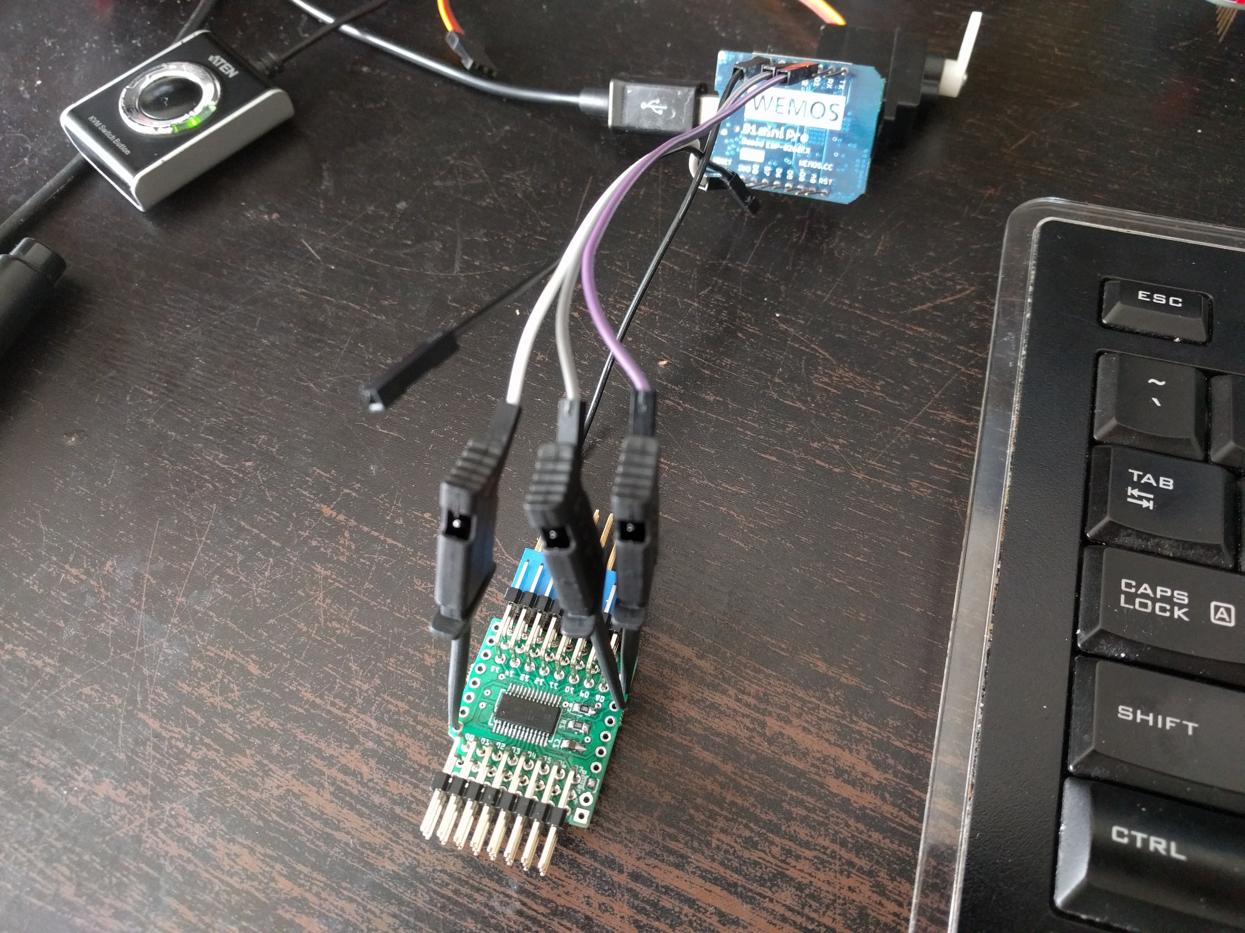
Frustrated, I swapped the D1 Mini board that I was using to test the I²C communication (MicroPython is super-convenient for that, as you can just type stuff at the console and have it execute live), for a Adafruit HUZZAH Feather, changed the pins from GPIO4 and GPIO5 to GPIO0 and GPIO2 (because they have pullups already), and... it still didn't work.
When I shared my frustration at the hacker channel, Christoph suggested I try with a slower clock. So I lowered the clock frequency from 400kHz to 100kHz, and it magically worked. That gave me an idea -- maybe the pullups are too weak for the faster speed? So I tried enabling the internal pullups on the ATmega (I know, I know), and it works at 400kHz now too.
Here's the code, if you are interested:
#define PWM_MAX_PINS 12
#define PWM_PERIOD 20000L
#include "pwm.h"
#include <avr/io.h>
#define I2C_ADDRESS 0x10
#define I2C_BUFFER_SIZE 32
volatile unsigned char *ports[PWM_MAX_PINS] = {
&PORTD, &PORTD,
&PORTD, &PORTD, &PORTD, &PORTD, &PORTD, &PORTD, &PORTB, &PORTB,
&PORTB, &PORTB, &PORTB, &PORTB, &PORTC, &PORTC, &PORTC, &PORTC,
};
unsigned char pins[PWM_MAX_PINS] = {
1, 0,
2, 3, 4, 5, 6, 7, 0, 1,
2, 3, 4, 5, 0, 1, 2, 3,
};
int main(void) {
unsigned char i2c_buffer[I2C_BUFFER_SIZE];
unsigned char i2c_cursor = 0;
unsigned char servo;
union {
unsigned char bytes[2];
unsigned int value;
} bytes2int;
pwm_init(ports, pins, PWM_MAX_PINS, PWM_PERIOD);
for (unsigned char i = 0; i < PWM_MAX_PINS; ++i) {
pwm_set_phase_batch(i, 0);
}
pwm_apply_batch();
PORTC |= 1<<PC4 | 1<<PC5;
TWAR = I2C_ADDRESS<<1;
while (1) {
TWCR = 1<<TWEN | 1<<TWINT | 1<<TWEA;
while (!(TWCR & (1<<TWINT))) {}
switch (TWSR & 0xF8) {
case 0x60:
i2c_cursor = 0;
break;
case 0x80:
case 0x88:
if (i2c_cursor < I2C_BUFFER_SIZE) {
i2c_buffer[i2c_cursor++] = TWDR;
}
case 0xa0:
if (i2c_cursor > 0) {
servo = i2c_buffer[0];
for (unsigned char i = 1; i < i2c_cursor - 1; i += 2) {
bytes2int.bytes[0] = i2c_buffer[i];
bytes2int.bytes[1] = i2c_buffer[i + 1];
pwm_set_phase_batch(servo, bytes2int.value);
++servo;
if (servo >= PWM_MAX_PINS) {
servo = 0;
}
}
pwm_apply_batch();
}
break;
}
}
}However, it turned out that all my effort is for nothing. While my I²C code is only about 250 bytes (already a quarter of the limit, if you think about it), the PWM code I'm using totals almost 3kB. I should have checked that before I started.
So no contest for this particular project, at least for now -- unless I manage to write my own servo PWM code that...
Read more »
 Radomir Dopieralski
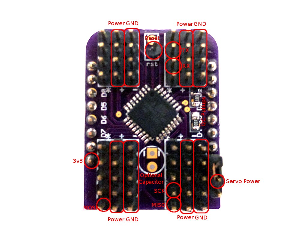
 I also wrote proper documentation manual for this board, it's available here:
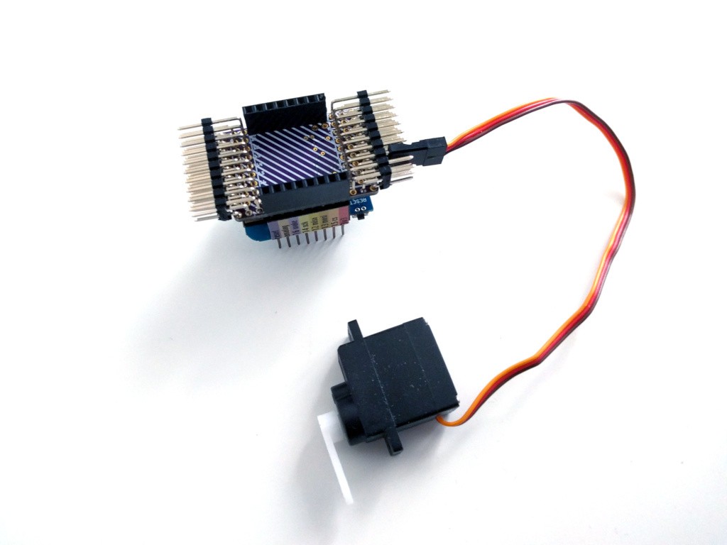


Maybe I've worked too long in the field of electrical reliability to put too much trust in the mechanical fitness of a two rows of 8 pin headers to support the mass of an assembly of a rather dense assembly [shield-PCB+48 pin headers+16 3pin connectors+attached cables]. It might be advisable to provide mounting options that take away mechanical strain and stress from the pin headers. Also such an assembly easily draws a lot of current, even if no servo is ever stalled (0.2A x 16). The requirements of an adequate power supply (with sufficiently designed ground) might also be a good thing to be getting aware of.