0%
0%
Servo Controller
Drive a dozen or more servos over serial or I²C, on the cheap
Drive a dozen or more servos over serial or I²C, on the cheap
I don't like leaving things broken, so I took some time to fix the mistakes on the PCB -- mostly make the pin holes proper size. I also added some more VCC and GND pins, so that it's easier to chain those boards.
I don't think I will be ordering more of them any time soon, but maybe someone will need them.
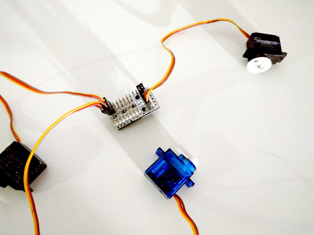
So, after some thinking I decided to actually use this, after all. I have the boards, and although they are not perfect, the problems with them can be worked around. And I have one robot that is particularly tight for space, and uses 18 servos, that I want to control with OpenMV. So it will be useful.
The first problem is that the holes for the pin headers are too tight. That is easily solved, like many things in life, with some unwarranted use of excessive force. I basically used a vice to force the pins in, and the soldered them on both sides, to make them safely secured in place. This required careful planning on the order in which I soldered them, but went well.
The second problem was the spacing between the Pro Mini and the servo board. I actually turned it into an advantage, by attaching the Pro Mini up-side-down, and hiding all the components on its surface in that gap.
Finally, the third problem -- the pins not sticking far enough to stick the servo plugs into them -- was simply solved by using longer pins, which I had lying around. This is not a good long-term solution, because most people won't have such pins, but it works for this single case.

I also wanted to write a library for Micropython for talking with this controller, but the code turned out to be so simple, that I don't think it makes sense to make a library:
import pyb
import struct

bus = pyb.I2C(2)
bus.init()

address = 0x09
servo = 4
position = 1500

bus.mem_write(struct.pack("<H", position), address, servo)
That's it.You can also move several servos at once, of course:
bus.mem_write(struct.pack("<HHH", position1, position2, position3), address, servo) Here's a shot of the PyBoard controlling it:
The PCB I ordered finally arrived, and I can't believe the amount of failure in it. Of course it's all my fault.
First of all, I used "small" holes for the pin headers, which are fine for female headers, but way too small for male ones. In particular, the pins of the Pro Mini wouldn't get through -- I had to drill those edge holes bigger. Fortunately they are not used for any connections.
Second, if you properly solder the pins, they will stick out a little on the other side of the board, so it won't be flat against the Pro Mini. Which is kinda obvious now. I had to solder them with very little sticking out, which makes them very fragile and easy to bend or break off.
Third, and that's made worse by the previous, the pins of the Pro Mini that actually reach the servo plugs are quite short. In fact, they may be too short for a proper connection.
In conclusion, I consider this project failed, especially since there are two great alternatives now, #SERVOcontrol and #Universal Servo Breakout. However, I will re-use the source code in my projects.
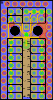
So this is my latest version of the PCB for this project:

I noticed, that the only connections that I actually need, are the ground and power pins. So I'm not going to rely on the alternating pin holes providing good connection for those, but instead use two jumpers. All the other pins are basically just for mechanical mounting, they are not even connected. I also added some pads for SMD capacitors, in case they were preferred over the through-hole one, and moved the power-in pins.
Unfortunately, I have no way to provide access to the I²C pins -- they clash with the power and ground rails for the servo plugs. They will need to be accessed from the other side.
This is the first time something like this happens to me, and I have to admit I'm very pleasantly surprised. You see, I described this project here, but am still working for the parts (in fact, still didn't send the PCB design to fabrication), and suddenly I get a message telling me that @al1 mentioned me and my project in his log update. I head over there, and what do I see? He build my project before I got a chance to even try it. That's what I call rapid prototyping.
In all honesty, @al1 didn't actually replicate my (as yet non-existing) project -- he actually improved on the design, and plans to use his own code. He also used a strip-board instead of a custom PCB and those long pin headers, instead of awkward hacks I'm planning to use.
I think I will steal some ideas from it.
OK, so that went quick. I just simply wrote an I²C receiving function using the Wire library, and we have a functional servo controller for 18 servos. The code is all in the repository, before uploading it with Arduino IDE you should set the desired I²C address. Of course, you can have multiple such controllers, each with a different address, each controlling up to 18 servos!
To set servos to specific positions, just send block data to the address of the first servo, two bytes per servo, denoting the duty cycle in µs. For example, on a Raspberry Pi you would do:
import struct
import smbus

bus = smbus.SMBus(1)
address = 0x09
servo = 4
bus.write_i2c_block_data(address, servo, [ord(c) for c in struct.pack("<H", 1500)])
You can even send the positions of up to 16 servos at once:
bus.write_i2c_block_data(address, servo, [ord(c) for c in struct.pack("<HHH", 1500, 1000, 2400)])And that's it. You can't read those positions, maybe I will add that later on, but honestly, why would you want to read them. To power down a servo, set the duty cycle to 0.
The default library in Arduino can handle 12 servos at once on the Pro Mini. This is already quite useful, but if you look closely, there is a total of 20 pins that can be used for digital output. We will need two of them for I²C, but the rest could be used for servos. All we need is a library that handles that.
When @The Big One constructed his #Stubby the (Teaching) Hexapod, he had to write such a library that could handle 18 servos at once. I took the liberty of borrowing his code, and with just minor adaptations for the ATmega328p and accounting for the Arduino environment, I got it working. There were two issues to be solved.
First, the code refused to compile. That was because ATmega328p has no PORTA port, and because some of the syntax in the C file required C99 dialect. @The Big One told me about the PWM_PORTA_UNUSED macro that avoids the former, and renaming the file to "pwm.cpp" resolved the latter.
Second, the PWM signal generated stubbornly had about 6.1Hz instead of the requested 50Hz. After some experimenting with my new oscilloscope, I determined that the problem only appers when the prescaler is set to 1 or 8, and not when it's set to higher values. That kept me lost for several hours, until, in a flash of intuition, I added zeroing the timer prescaler bits, instead of just setting the ones that were supposed to be 1. Turns out the Arduino code apparently sets its own prescaler for that timer, and the two settings were getting OR-ed.
So for now I have code in the repository that sets 18 servos to their centers and then proceeds to doing nothing at all. Now I just need to add some basic I²C communication there.
There has also been some progress on the hardware part of the project. The prototypes so far were made using a stripboard, but now I want to have a proper PCB. I figured out that if the PCB itself is thin enough, and the holes for the signal headers are alternating, I could simply plug that PCB under the actual Pro Mini without soldering, and maybe add two jumpers to make sure the power connection is good. I designed a board with that in mind:
 It even has room for an optional capacitor! I didn't order it yet, however, because it's considerably smaller than the 5×5cm limit, so I can panelize and get several boards in a single order.
This is really very simple, and in fact, I've been using such servo drivers for various projects for quite a while, for instance in #µKubik quadruped robot. But now I want to actually design a proper PCB and write proper, universal, code. The PCB would go on the back of the Pro Mini, saving a lot of space. It would be something like this:

It's mostly servo sockets, with a room for an optional capacitor, a power plug, and a jumper for connecting the Arduino's power with the servo power, if you want to power them from the same source. The I²C pins are not included, because they would need to be accessed from the other side, otherwise I would have to have 3 servo sockets fewer.
As for the code, so far I've used very simple approach, using the Arduino's "Servo" library, which can handle up to 12 servos. If I manage to use a custom library instead, I can use all the pins -- up to 18 servos (assuming I²C control, because the serial pins would be used by servos too). There would need to be some configuration in the code -- whether to use the serial pins for servos, and the I²C address to use, etc.
 Radomir Dopieralski