What if #Katka and #µBob had a child? A robot the size of µBob, but with four legs and eight servos like Katka? I had this idea in the back of my head ever since I saw that the Servo library for the Arduino core for ESP8266 supports servos on all the available pins (and more).
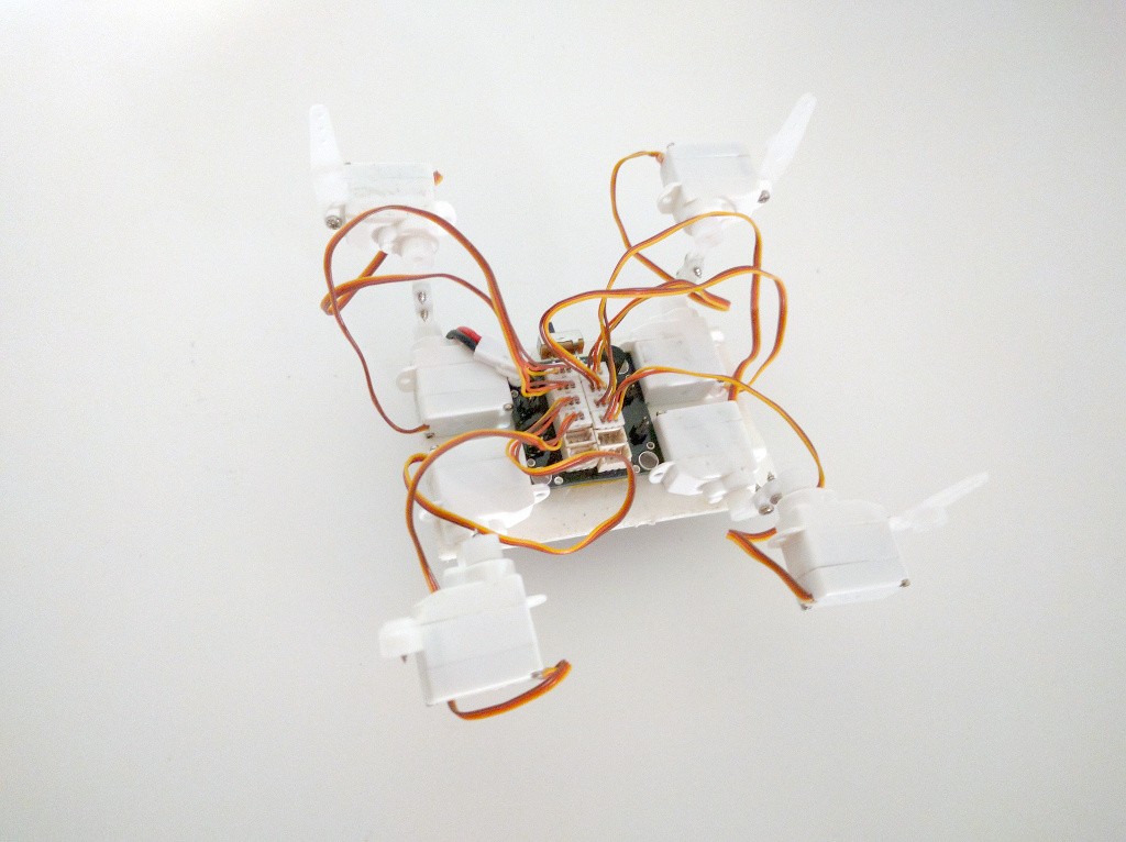
Mechanically µKatka is more or less complete -- there might be some further improvements in order, but the basic functionality is there. Electrically it's finished too. The last thing that is left is software. Using the Arduino ESP8266 core, I wrote a simple server that listens for commands and sets the servo positions accordingly.
Of course this is still not a complete, working robot -- the remaining part is a Python script for the PC that would send the correct positions for walking. As I'm traveling until the end of the year, this will have to wait a little bit.
After testing it with eight servos, I decided it's time to actually give it a proper body. So I took my trusty screwdriver, put together the servo horns to form legs, and glued it all with two-sided tape to a piece of plastic. Then I switched it on, and observed blue smoke from the servos.
I immediately switched it off, disconnected the smoking servo and tried it again, to see if the board still works. It worked, but after a moment there was blue smoke from a second servo, and it stopped working. And the power switch became very easy to move.
So I took a closer look at the burned servos. Sure enough, the insulation was all burned near where the wires go into the servo, and all three leads were touching. I took a look at the remaining servos. Most of them were fine, but two had naked wires close to where they enter the servo -- the insulation started about 1mm farther. So that worked fine as long as the wires didn't move, but wiggle them around a bit, and it explodes.
I replaced the power switch and the two burned servos, and I put a drop of glue on every servo where the wires come in, to avoid this in the future. Now all that is left is to adjust the servo horn positions and program this thing.
So yeah, the board doesn't boot (or maybe boots into some weird mode) when there is a servo connected to the TX pin when it's switched on. The servo basically acts as a pulldown resistors here, connecting the pin to the ground through some load, so I assume this is some undocumented feature of the ESP8266 chip. If you know what it actually is, please let me know!
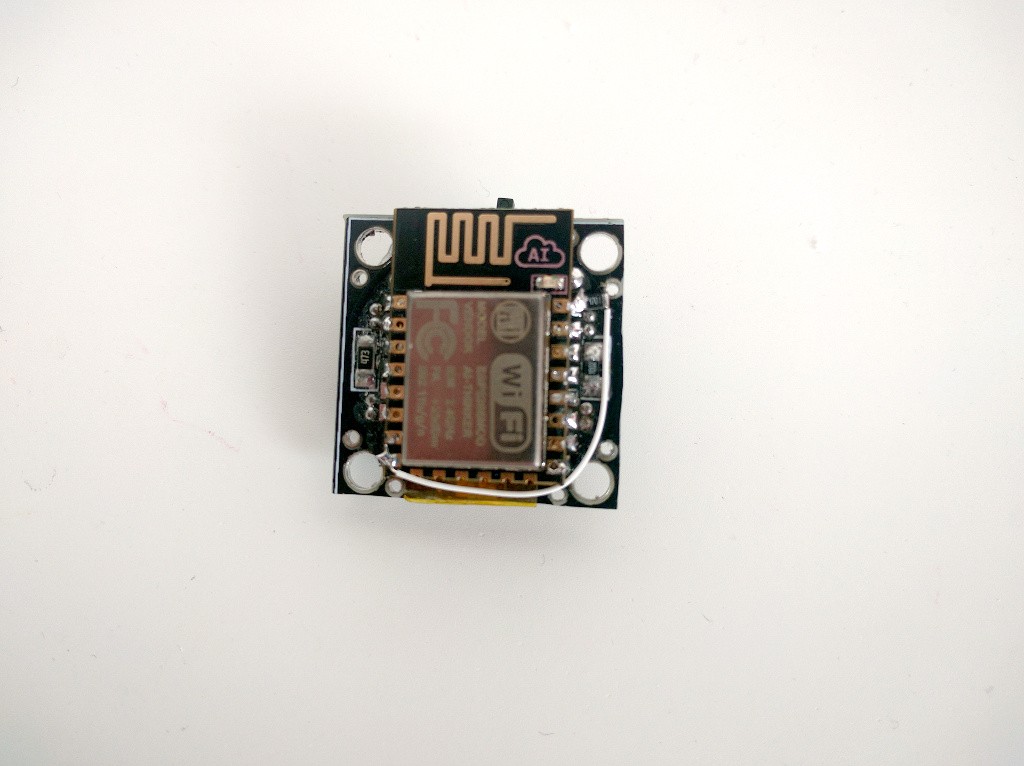
Knowing that, there is a way around this. You see, the small sub-micro servos that I am using are actually digital servos, and they have quite good sensitivity for the signal. Basically anything strong enough to trigger an interrupt on voltage change edge will work. That means that we can add a pull-up resistor small enough to keep that pin high while the board boots, but large enough for the board to be able to still pull the pin down low enough for the servo to register. After some short experimentation with different values, I settled with 4.7kΩ resistor:
Of course there is no time to redesign and order a new PCB, so I just soldered an additional SMD resistor directly to the pin, and used a short piece of wire to connect the other end to power. It doesn't look very bad, and it makes the thing work properly.
Here's a video of the board driving eight servos at once:
Of course that's not all yet. I still need to connect all the servos mechanically to make the robot's legs, and to adapt Katka's gait code for the smaller dimensions. Hopefully I will be able to do that soon.
So after some pause I came back to this project. The servo driver really gave me a lot of grief -- the individual servo sockets worked randomly, the board seemed to randomly restart, hang or sometimes not boot at all. After some advice on the ESP8266 channel on Freenode, I tried adding some serial messages for debugging, and that let me see that the board indeed crashes with some "failed to fetch instruction" errors. I tried the code on an ESP8266-12E board from a different source, and sure enough it worked. So I desoldered the original board and replaced it with the working one. China...
Anyways, I can drive up to 10 servos now, with a caveat. The problem is that the servos on pins TX, GPIO02 and GPIO15 can't be connected while the board boots -- otherwise the board doesn't boot into the right mode. So I have 7 servos working normally, and 3 additional ones that you have to connect after the board boots... Not perfect.
I will experiment further with some pullup resistors -- I might be able to make at least one more servo work, which would be enough to have µKatka walking.
Hmm... seems like I've been too optimistic and trusting about the ESP8266 Arduino Servo library. It does seem to work on all the pins, but the signal it generates doesn't work with those small servos properly -- they all move to their limit and stay there, while they should be sweeping...
Last time I had such problems, it turned out that I compiled the code for the wrong microcontroller speed, and the signal was actually 100Hz instead of 50Hz. Unfortunately, I don't have an osciloscope or a logic analyzer handy to check that. So I made a small detour and now I'm trying to make the #BeagleLogic work on my BegleBone Green.
I designed this servo breakout long time ago, and ordered the PCB together with some other small projects, to fill the free space on the 5×5cm boards. I wrote about that back then. I even assembled one of the boards, but it didn't work right away, and I never had the energy to debug it. Today I picked it up again, and figured out that the problem is one of the pull-down resistors, on GPIO15. Turns out that 47kΩ is too much, and when I replaced it with a 10kΩ one, everything worked!
The board has a fun trace layout, because it was sitting on my disk for quite long time and I played with it a lot. As it happens, it's exactly one inch by one inch, which means that I may submit it to #The Square Inch Project now...
 Radomir Dopieralski
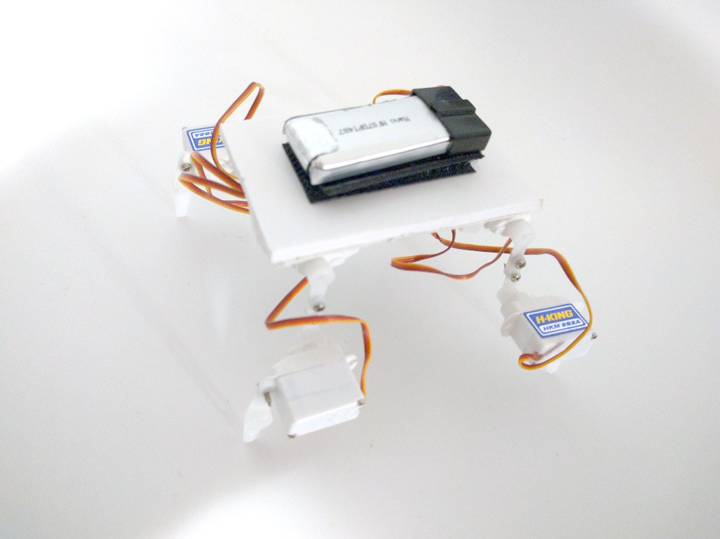


 Ryan Mitchell
Just a friendly reminder to please upload your gerbers by 23:59 UTC on Dec 8, 2015 to be in the running for #The Square Inch Project!