OSH Park
Shared projects
OneTube nixie clock
by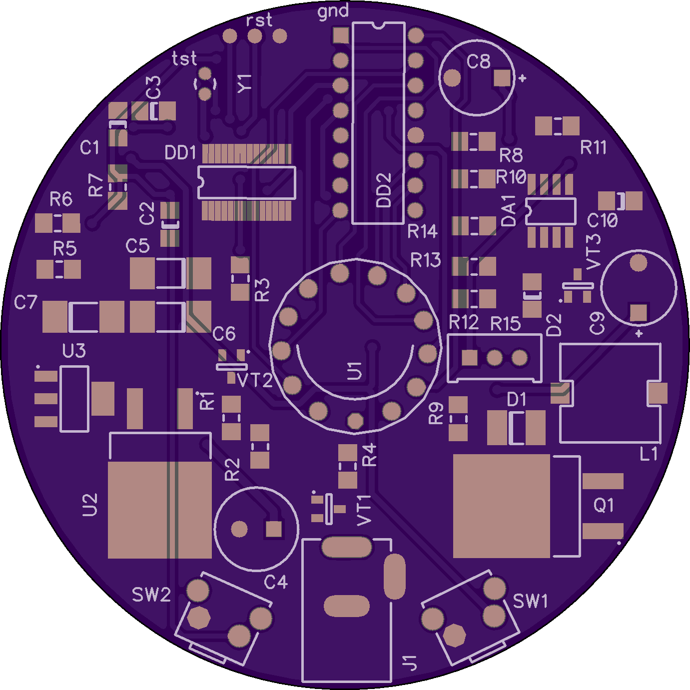

2
layer board of
2.76x2.76
inches
(70.15x70.15
mm).
Shared on
August 12th, 2015 07:24.
Nixie clock with only one IN-14
DRA818 daughter card version 1.2
by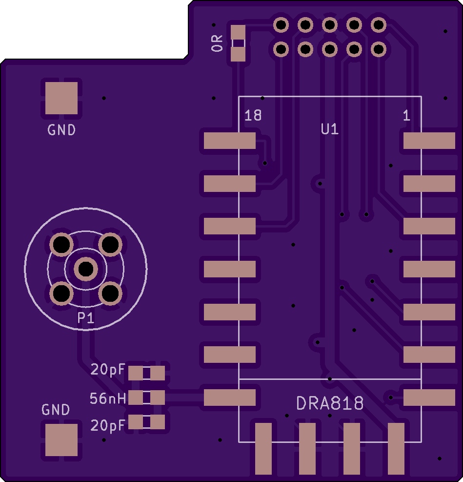
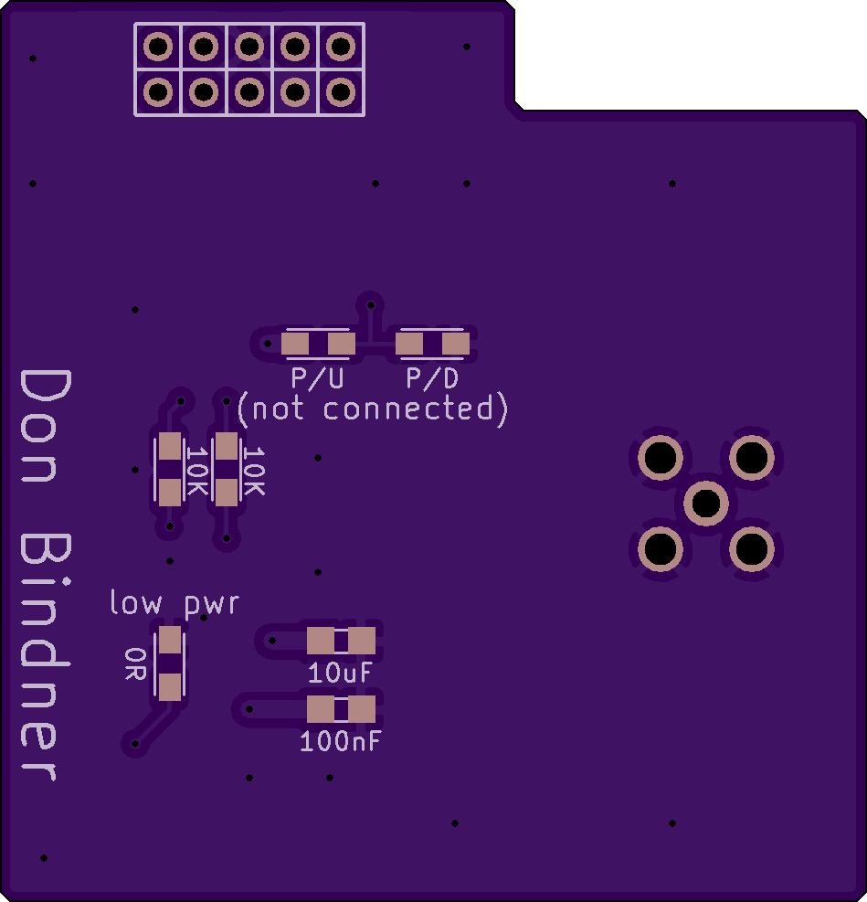
2
layer board of
1.90x1.97
inches
(48.23x50.14
mm).
Shared on
August 12th, 2015 03:22.
Plugs into balloon radio card to provide a transmitter. (This version with resistors in the PTT and Enable lines).
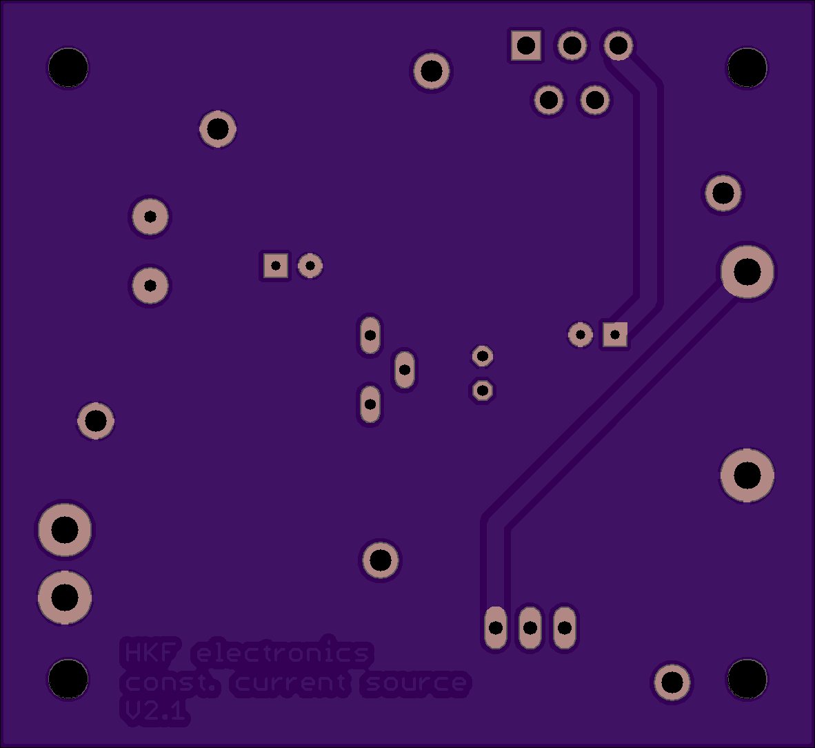
1Amp constant current source for milliohm meter
by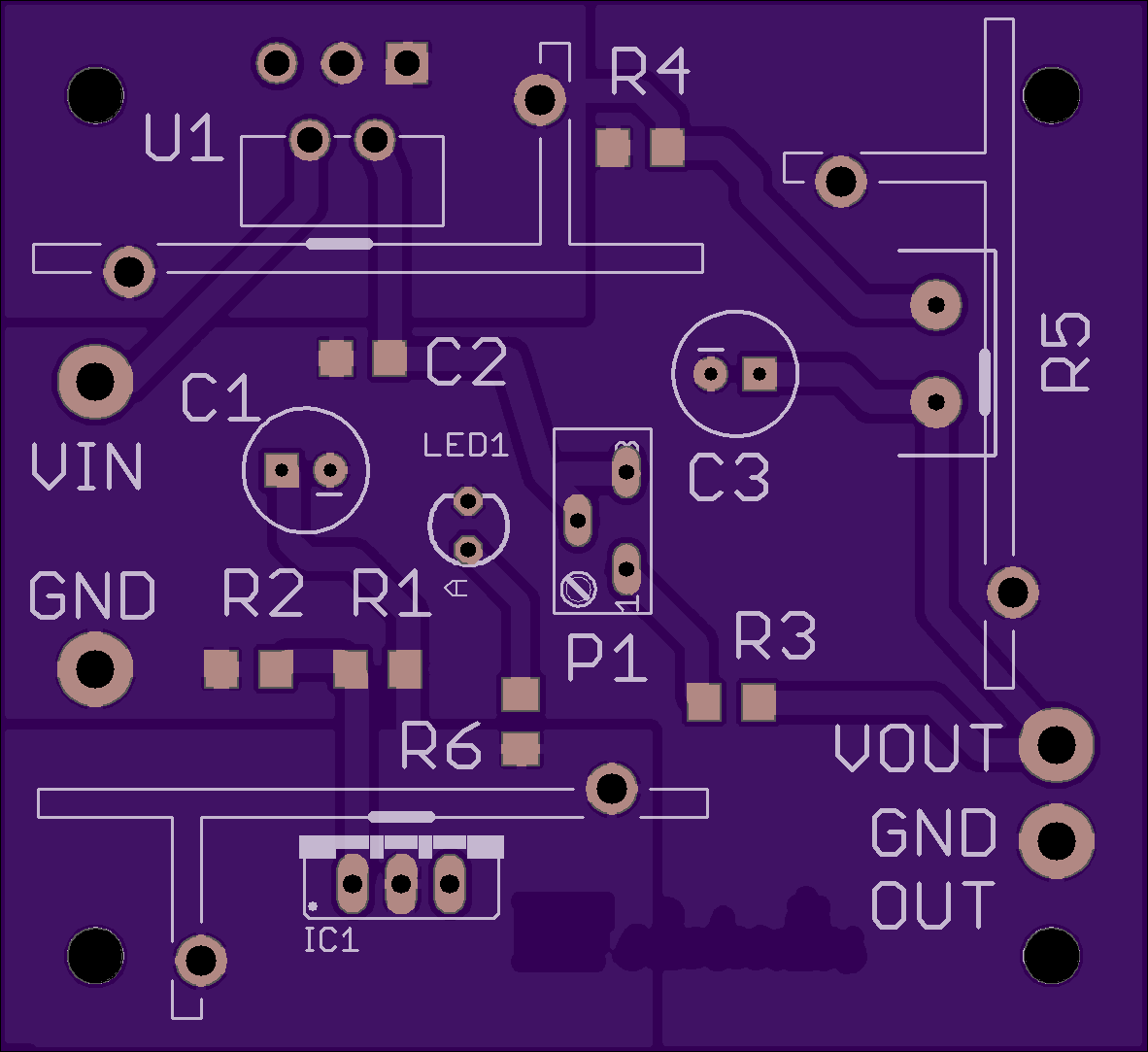
2
layer board of
2.36x2.17
inches
(60.02x55.02
mm).
Shared on
August 11th, 2015 23:13.
1Amp constant current source. You can use this constant current source to measure very low resistances since the voltage drop is R=V/I i.e. 1mV over each 1mΩ.
To guarantee correct operation and not thermally overstress IC1, U1 and R5 keep input voltage between 6.5V≥Vin≥9V
Calibrate with P1 to achieve exactly 1Amp at output with short circuit load or 1V with 1Ω resistor load.
BOM: IC1 LM317T; U1 LT3083; R1 1K6; R2 3K9; R3 18K; R4 910R; R5 1R 0.1% 1W; R6 130R; P1 5K 10turn precision poti; C1 10µF/5V tantal; C2 15pF ceramic; C3 10µF/5V tantal; LED1 green; heatsink of maximum 3K/W or lower for IC1, U1 and R5;
For schematics look here: https://www.dropbox.com/s/cs31b9lijhswvi1/1Amp%20constant%20current%20source.pdf?dl=0
For thermal calculation look here: https://www.dropbox.com/s/gdbk54ipaouoct8/1Amp%20current%20source%20thermal%20calculations.pdf?dl=0
Have fun!
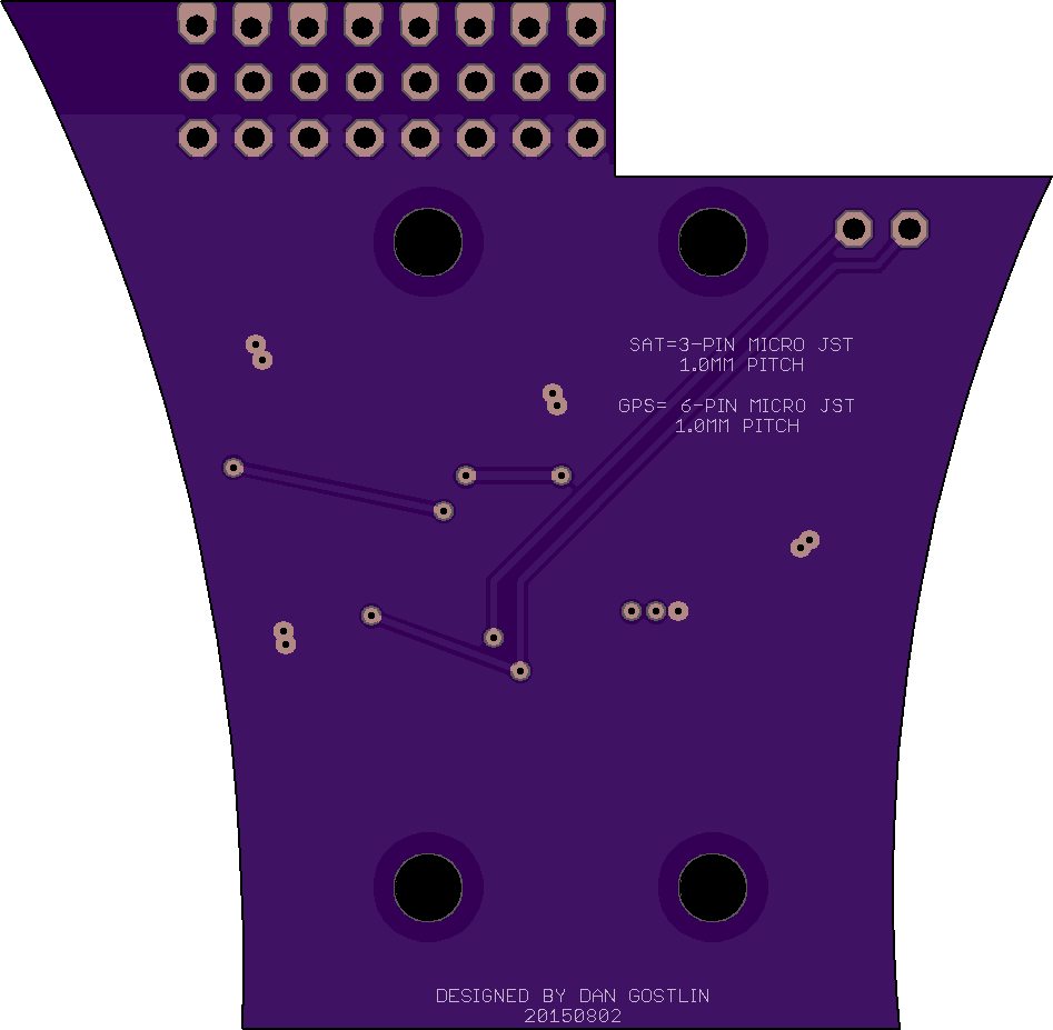
Full Naze32 Tricopter expansion board
by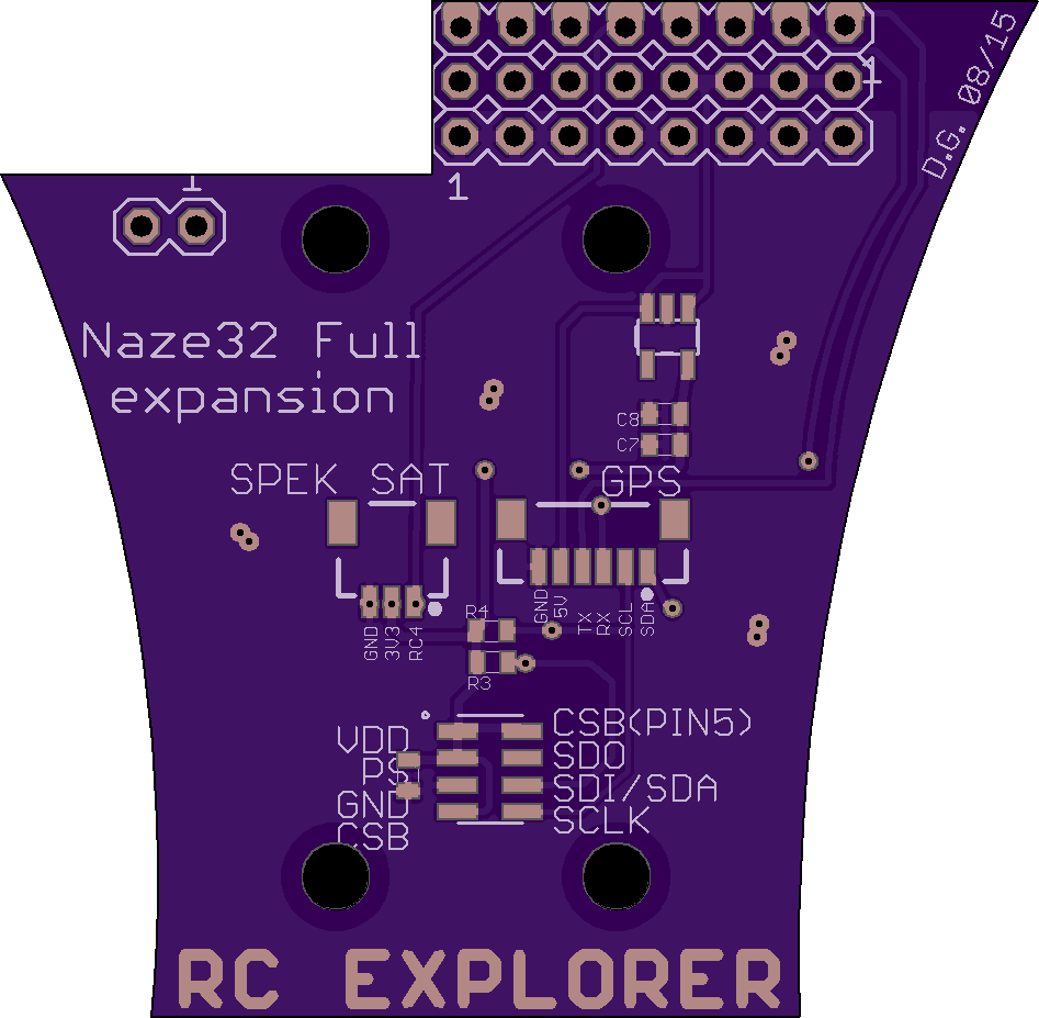
2
layer board of
1.89x1.86
inches
(48.11x47.12
mm).
Shared on
August 11th, 2015 21:06.
DO NOT ORDER, NOT READY, DOES NOT WORK!
QPD Circuit v2.0
by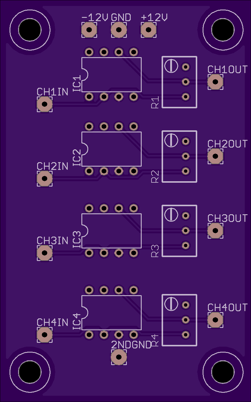

2
layer board of
1.69x2.70
inches
(42.85x68.58
mm).
Shared on
August 11th, 2015 18:17.
Lab 26’s Quad Photodiode amplifier circuit second edition