Very interesting, I've known about this phenomenon for a while, but haven't ever really looked much closer into it.
There's three things at work here.
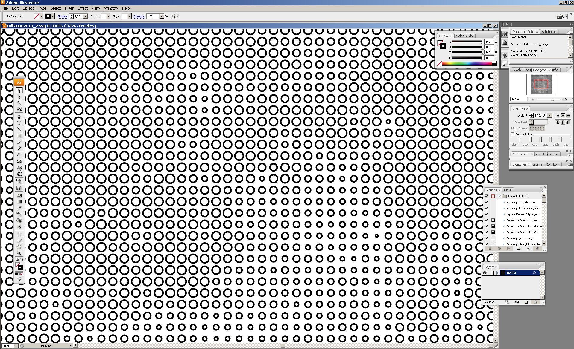
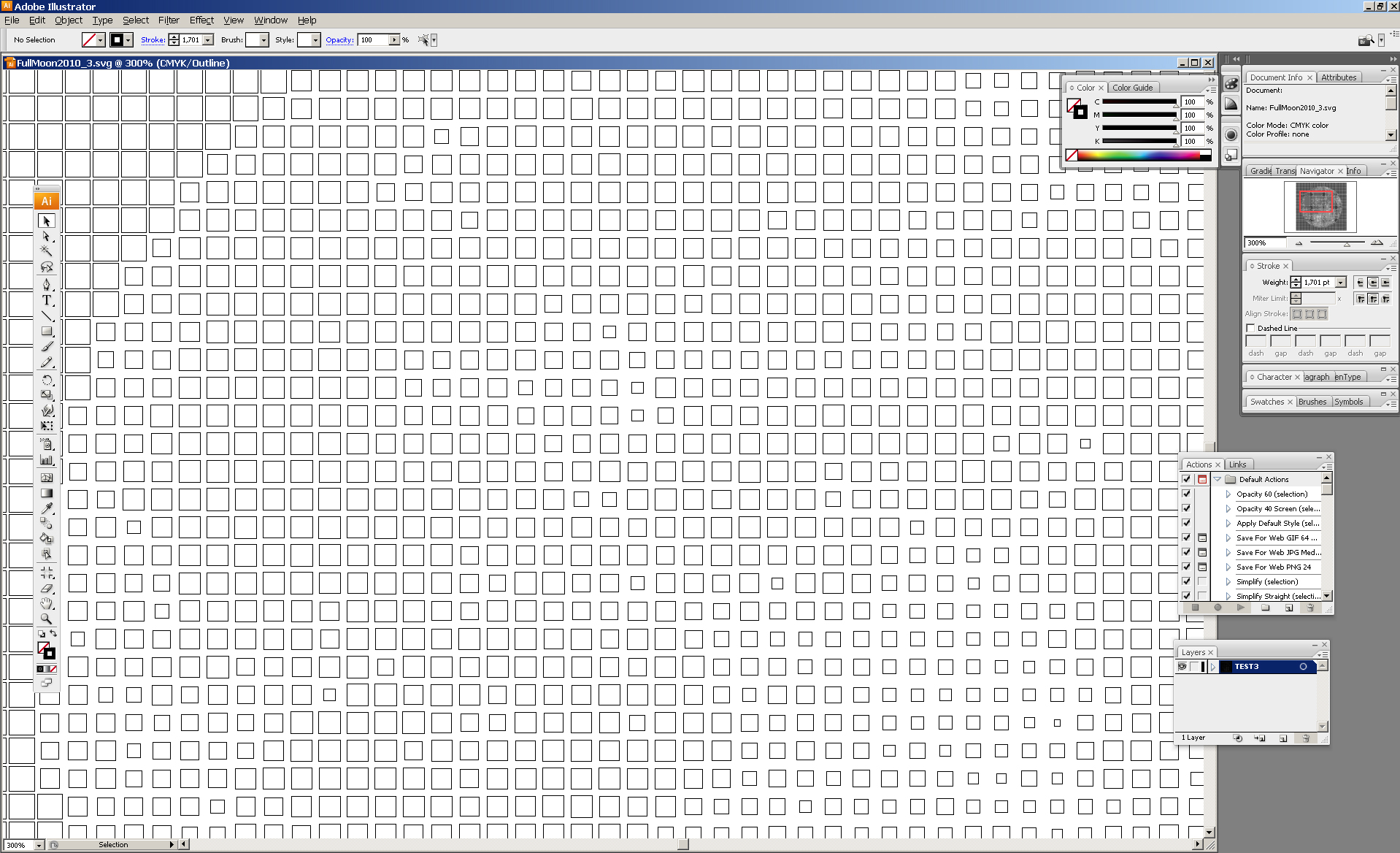
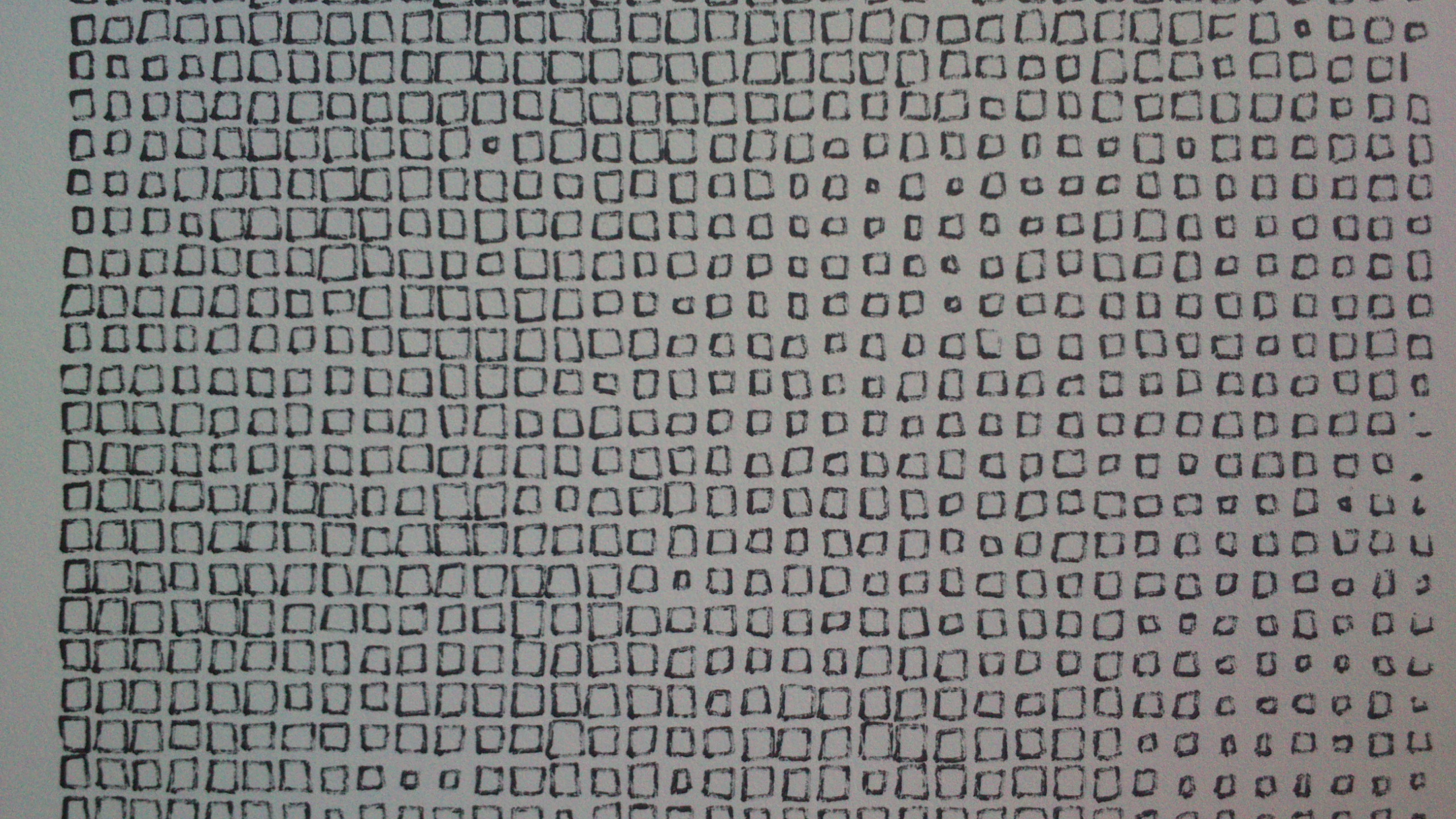
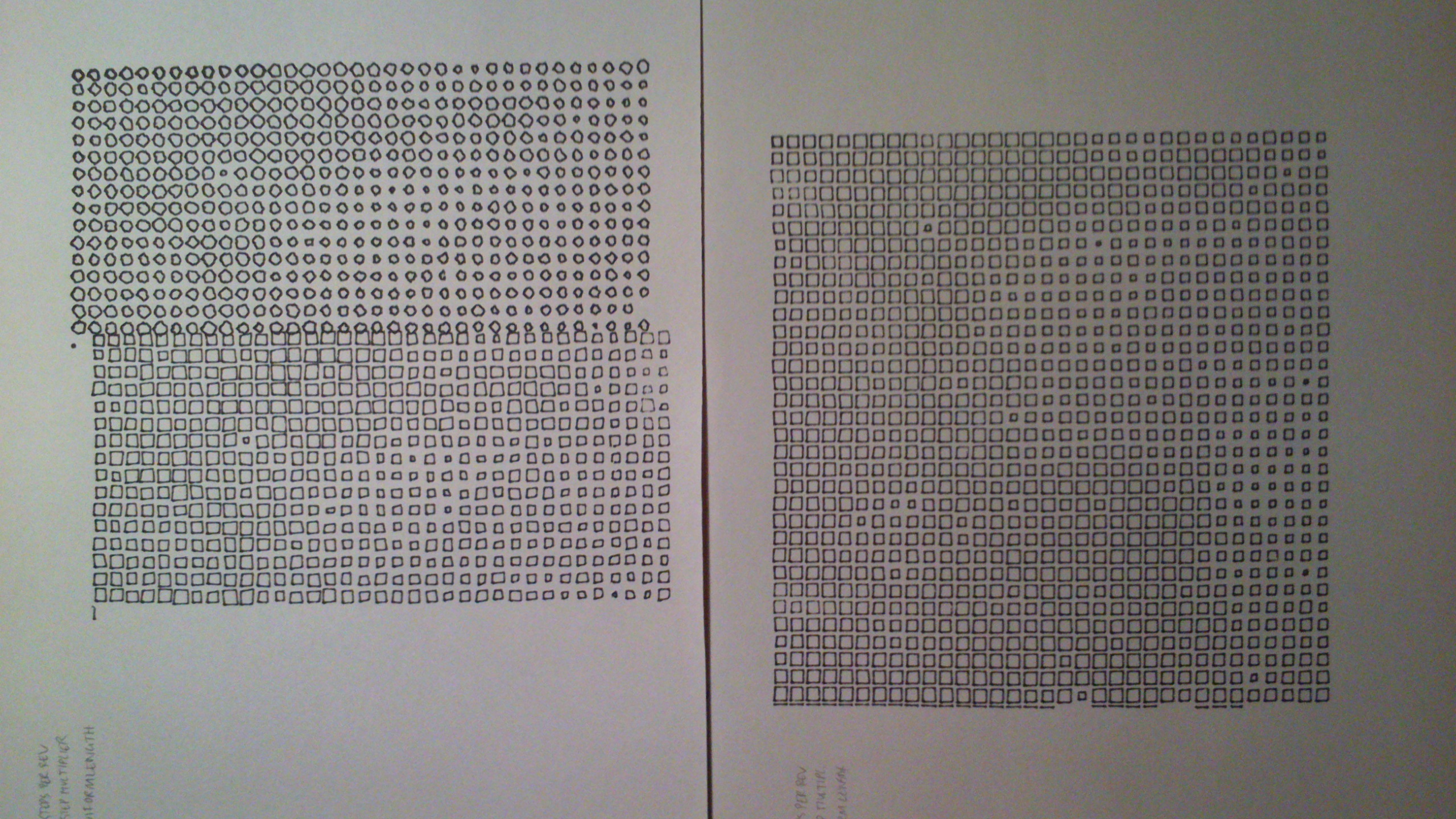
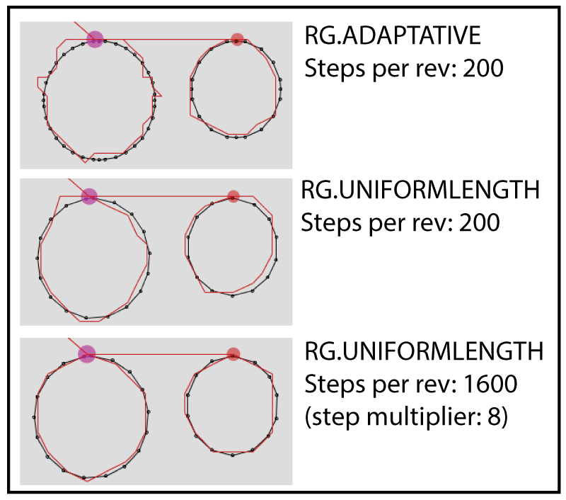
1. Polygonizing. Geomerative has a way of converting curves into polygons. The method that the Polargraph Controller app uses is called RG.ADAPTATIVE, but there's an alternative called RG.UNIFORMLENGTH and seems to result in a more regular output. You can change which it uses by modifying the line: https://github.com/euphy/polargraphcontroller/blob/master/polargraphcontroller.pde#L540
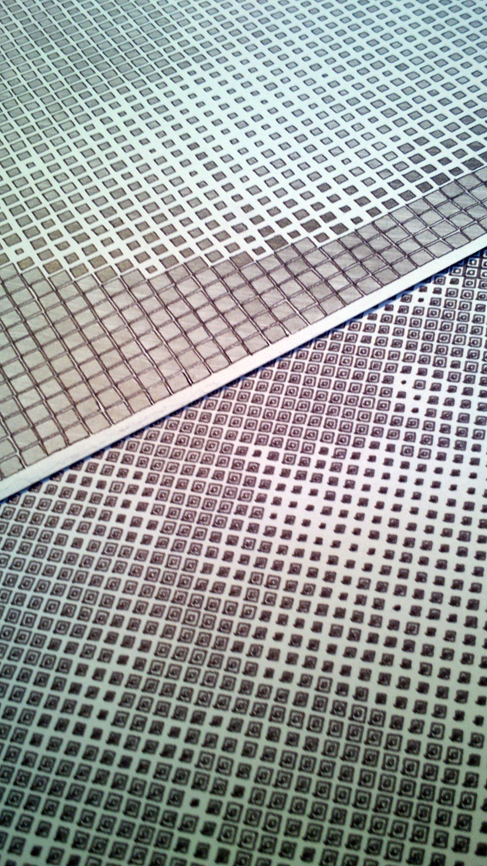
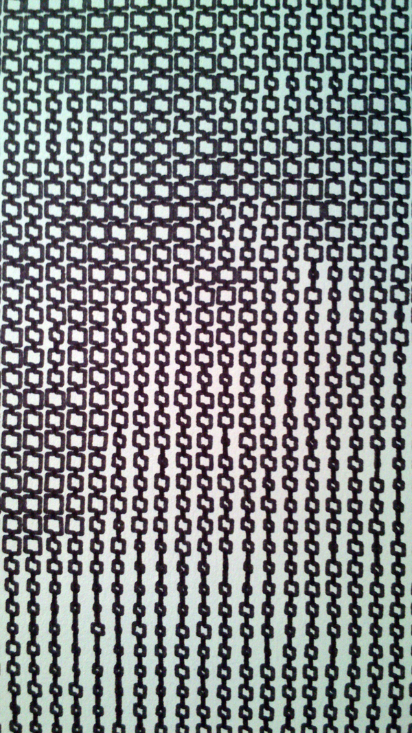
See pic at the bottom to see the difference it makes.
There's also a couple of extra functions in Geomerative that you can use to change how curves are polygonized:
    setPolygonizerLength

    public static void setPolygonizerLength(float length)

    Use this to set the segmentator length for the UNIFORMLENGTH segmentator and set the segmentator to UNIFORMLENGTH.

    Parameters:
        length - the length of each resulting segment.

    setPolygonizerStep

    public static void setPolygonizerStep(float step)

    Use this to set the segmentator step for the UNIFORMSTEP segmentator and set the segmentator to UNIFORMSTEP.

    Parameters:
        step - if a float from +0.0 to 1.0 is passed it's considered as the step, else it's considered as the number of steps. When a value of 0.0 is used the steps will be calculated automatically depending on an estimation of the length of the curve. The special value -1 is the same as 0.0 but also turning of the segmentation of lines (faster segmentation).
(from http://www.ricardmarxer.com/geomerative/documentation/geomerative/RG.html#polygonize%28geomerative.RShape%29)
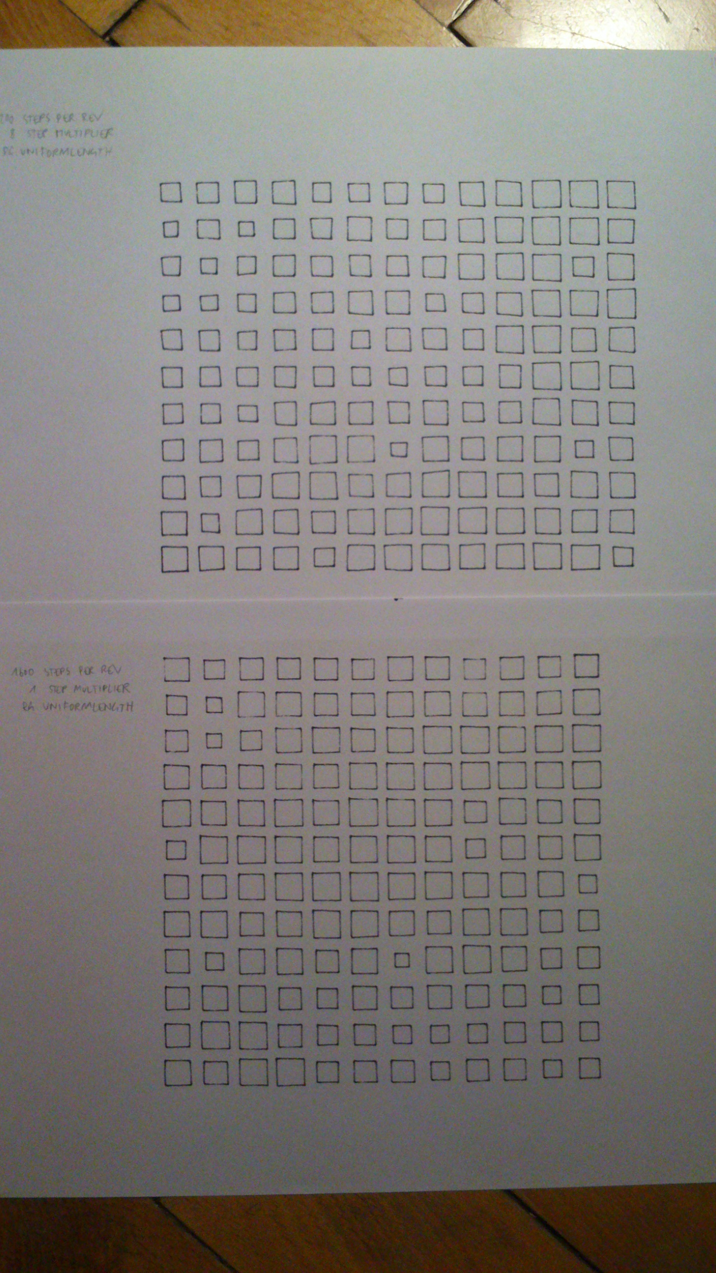
2. Basic resolution. There isn't actually a ton of physical resolution to the machine, but there's a little more to dig out if you need it. The steps per rev is set to 200, and the step multiplier is 8. So that means that there are 8 microsteps in between each full motor step. The machine is addressed using full steps, but moves in microsteps. The reason is that microsteps are unreliable - if you stop on a microstep then the motors get hot and the movement is unreliable. You can never be sure where it picks back up from, and it could be as much as half a full step out - and the errors will compound. As long as you aren't planning on leaving the machine motionless for more than a minute or two, you can use microsteps to address the machine too. Open your properties file and change
machine.motors.stepsPerRev=1600.0
machine.step.multiplier=1
This will give you a bit of extra resolution. It makes me uneasy! See pic at the bottom to see the difference it makes.
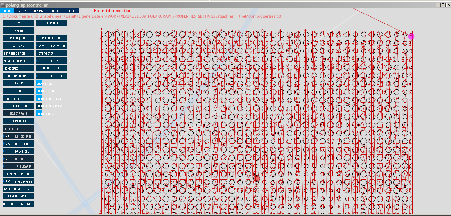
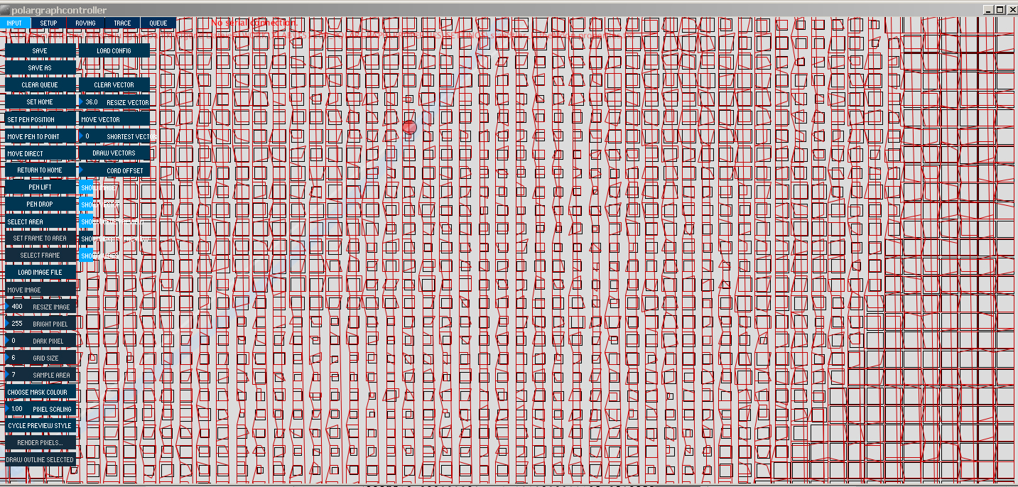
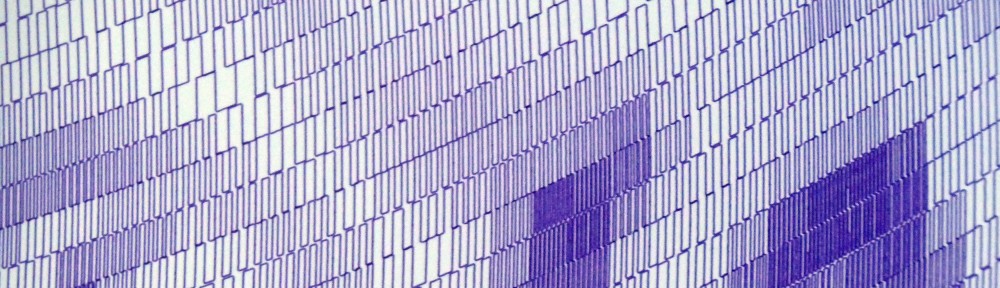
3. Last thing - plotting using the wrong coordinates system. Just looking at the shapes from the queue preview (the red lines), it's obvious that they're snapped to a cartesian grid, whereas the commands themselves use a native coodinate system. During the preview phase, the commands are grabbed from the queue, converted back into cartesian, then scaled to the screen. So the jagged edges on the screen don't necessarily correspond to the jagged edges that get drawn. HOWEVER, if they are distorted on-screen, then I think there's probably a pretty good chance they'll be distorted on paper too - just slightly differently. The degree of distortion is probably a good indicator.
I can think of a solution to this, but it doesn't do anything to get extra fidelity onto the page, so I'm not that interested in doing it.
~
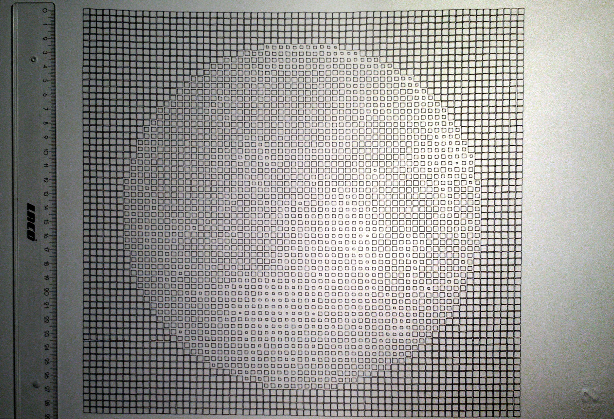
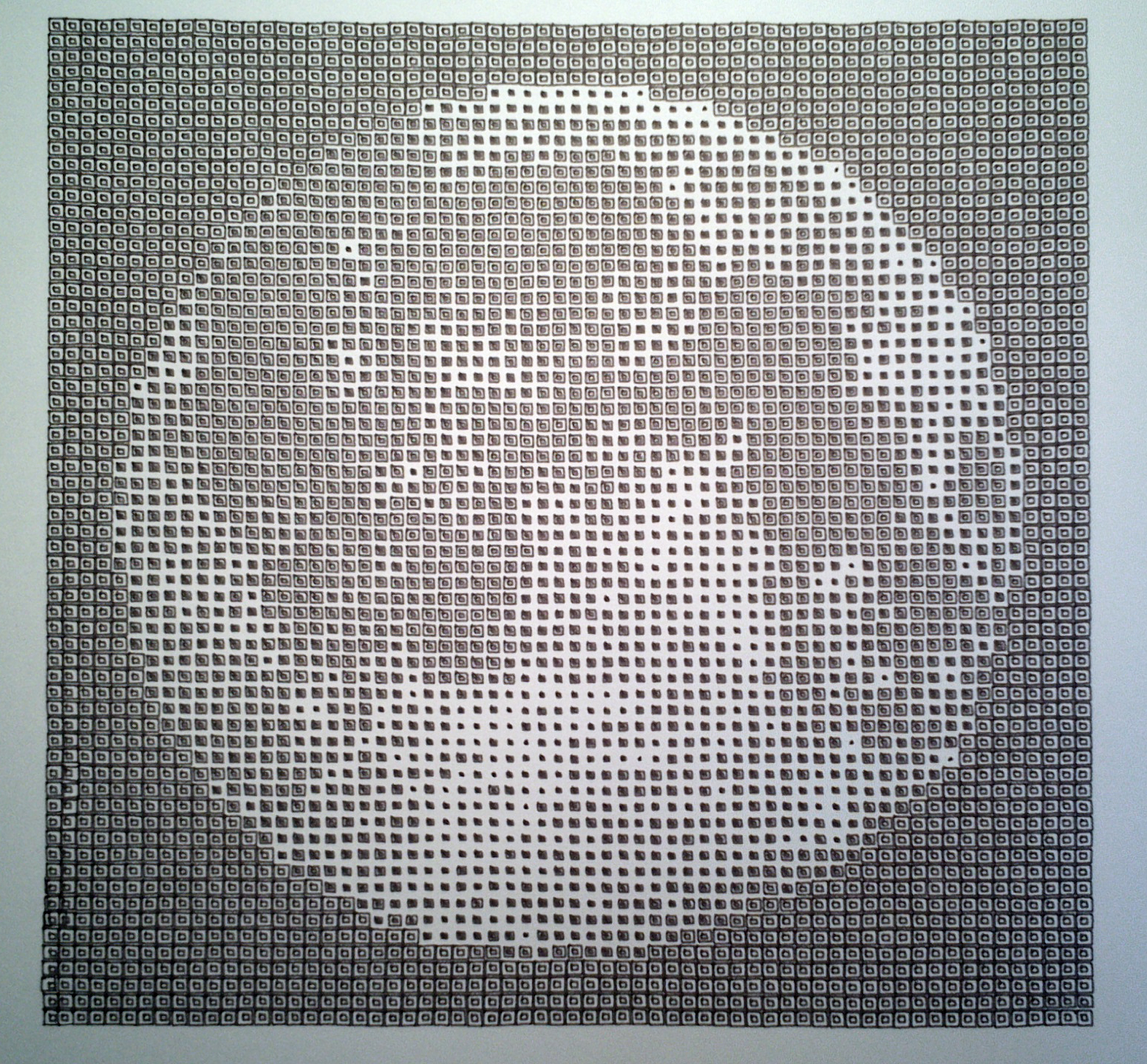
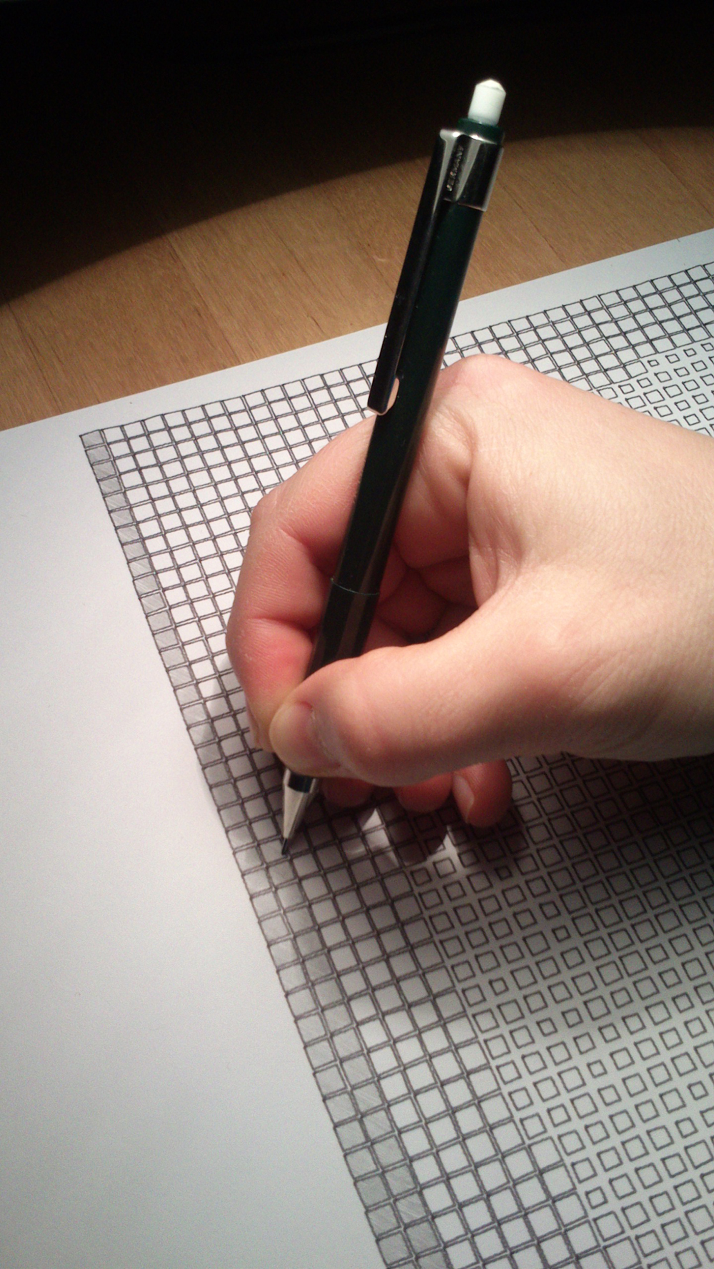
Here's a pic showing improvements that can come from changing the polygonizer style, and increasing the steps per rev.
|
 Author
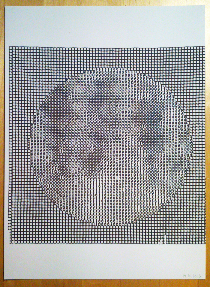
 Saw tooth circle and dubious text