Polarshield v3.0

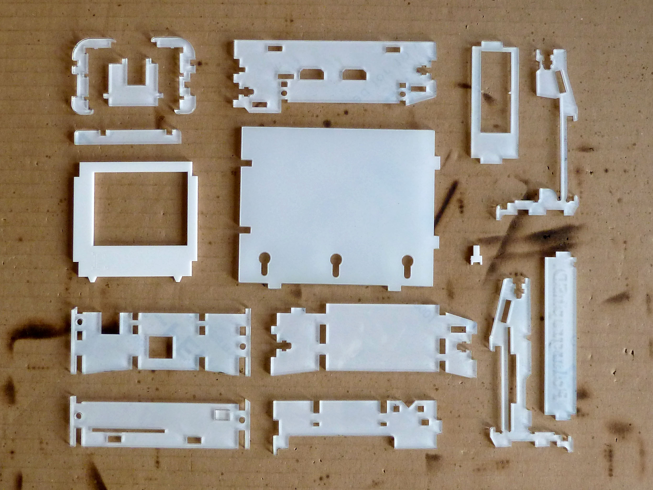
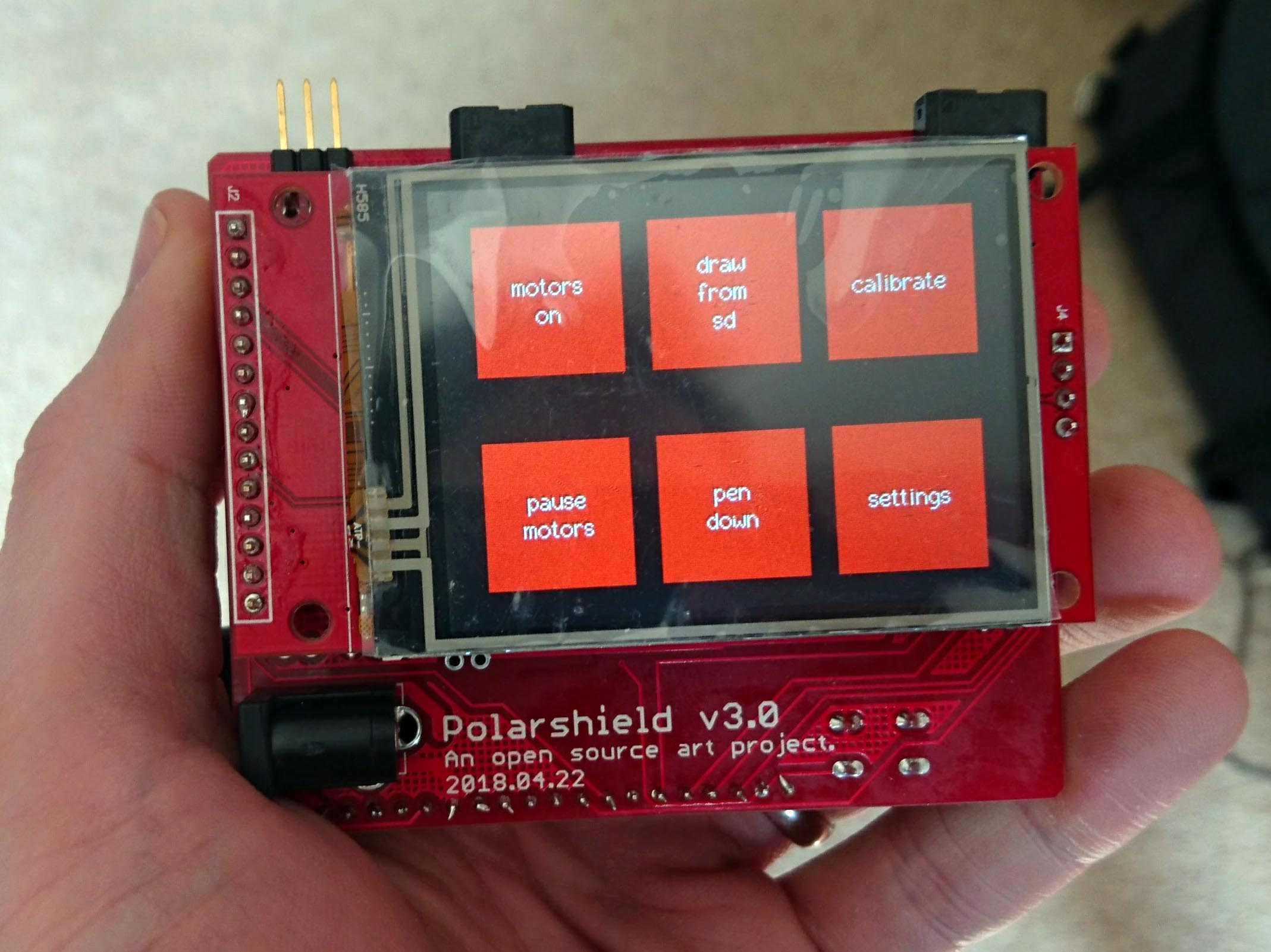
The new Polarshield v3.0 is a refreshed version of the core Polargraph hardware. It has been re-designed from scratch and snips out a few of the snaggles that the old machine had.

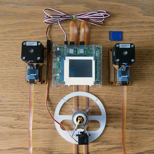
It allows integration of:

  • Espressif ESP-32 based microcontroller
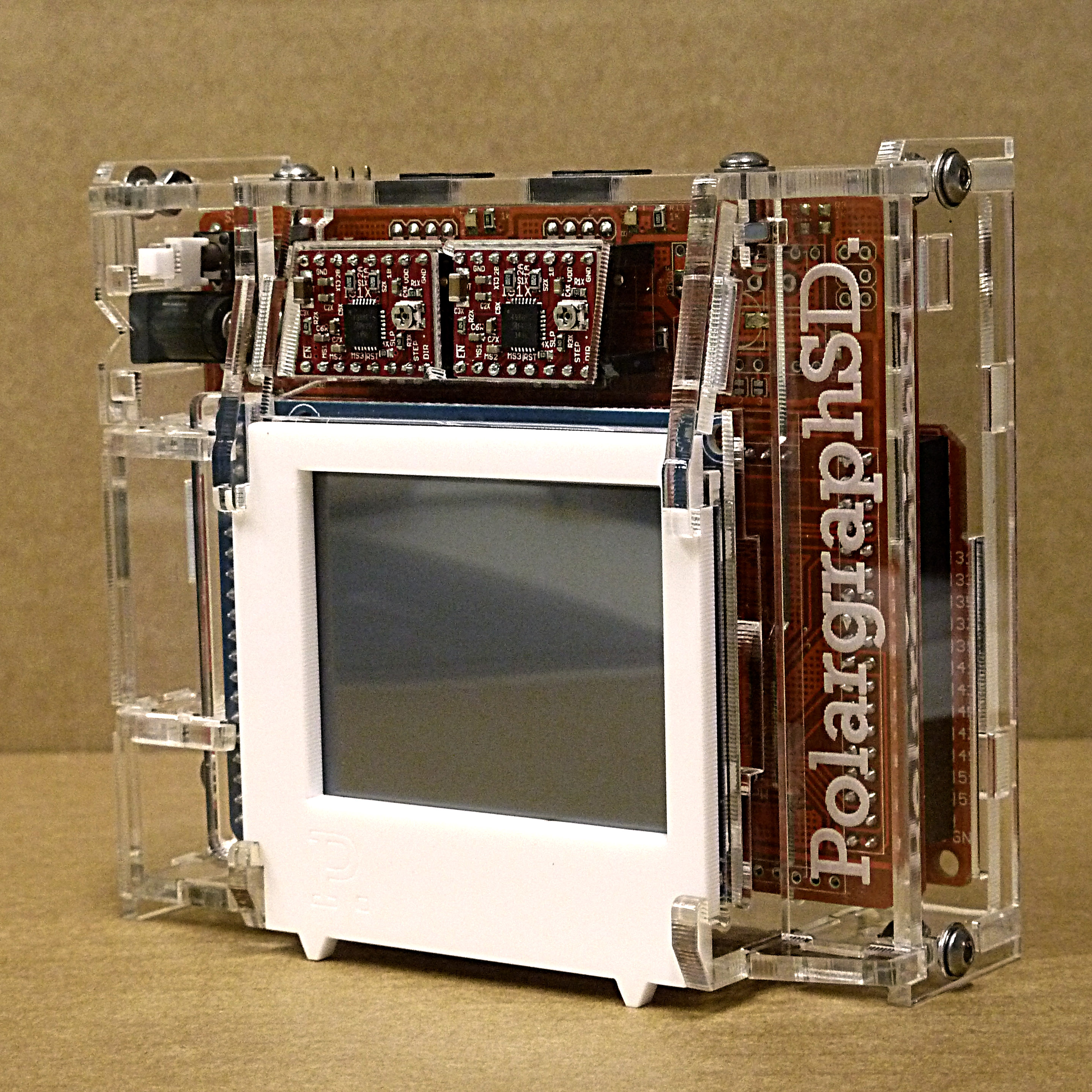
  • 2x A3988 stepper drivers
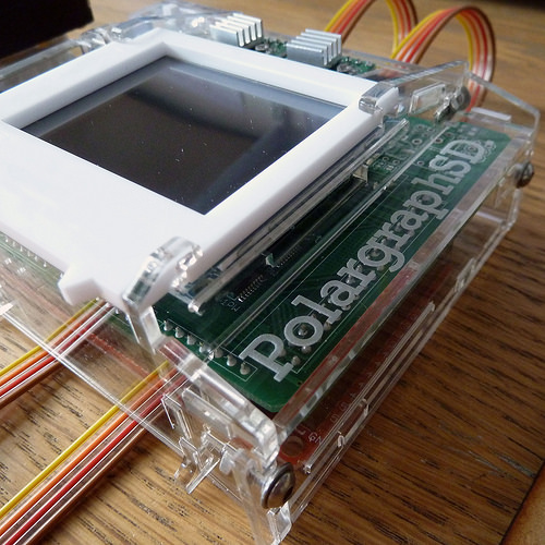
  • LCD and touchscreen
  • SD card for stored command queues
  • Servo for a pen lift

So the only real difference is the controller, which is a fast, 32-bit, dual-core device, with a real-time operating system (RTOS), oodles of memory AND built in bluetooth and wifi features. There is a working Arduino-based toolchain for this ESP-32 device, but it also has the horsepower and memory to run micropython.

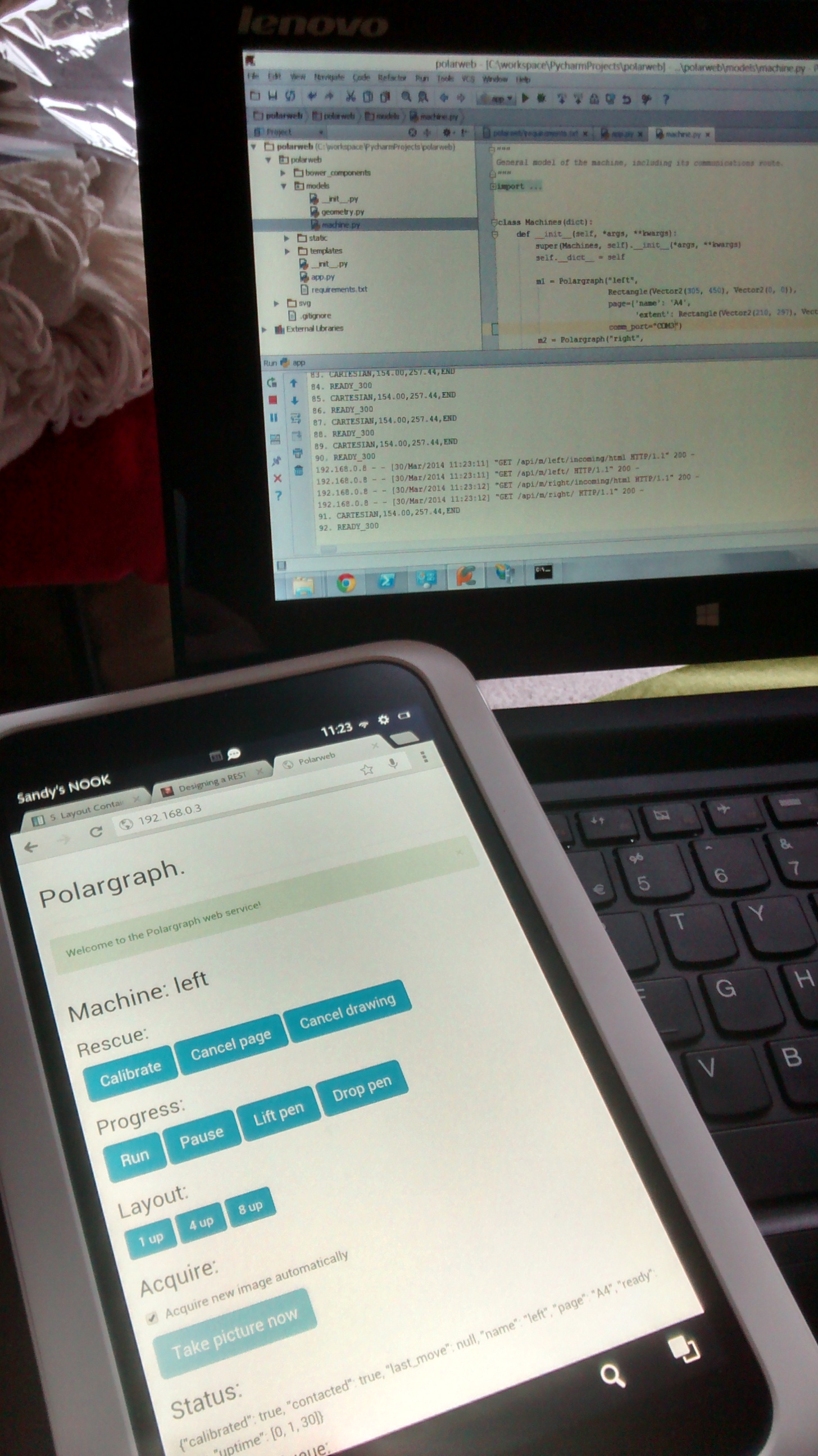
I’ve ported the standard polargraph_server_polarshield code to target this platform (in a branch – https://github.com/euphy/polargraph_server_polarshield/tree/esp32) and it works great … in principle. There’s a couple of bits don’t work yet, and I haven’t done any long drawings with it.

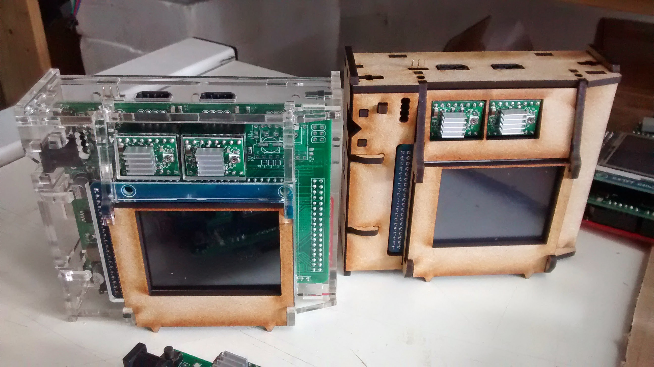
On the Polarshield itself, the hardware design is simplified because the ESP-32 is a 3.3v device and so are the stepper drivers, touchscreen and SD card, so there’s no need for level shifting. The LCDs are of a more modern and widely supported design too, so I expect to have fewer problems with them.

There are spare pins I’ve broken out for:

  • 2x motor shaft encoders for close-loop positioning
  • End stops for automatic calibration

I haven’t yet implemented any features around the encoders, endstops, wifi or bluetooth, and might never do that.

Why the change?

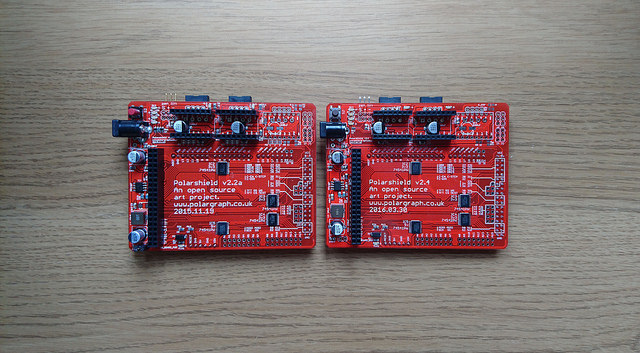
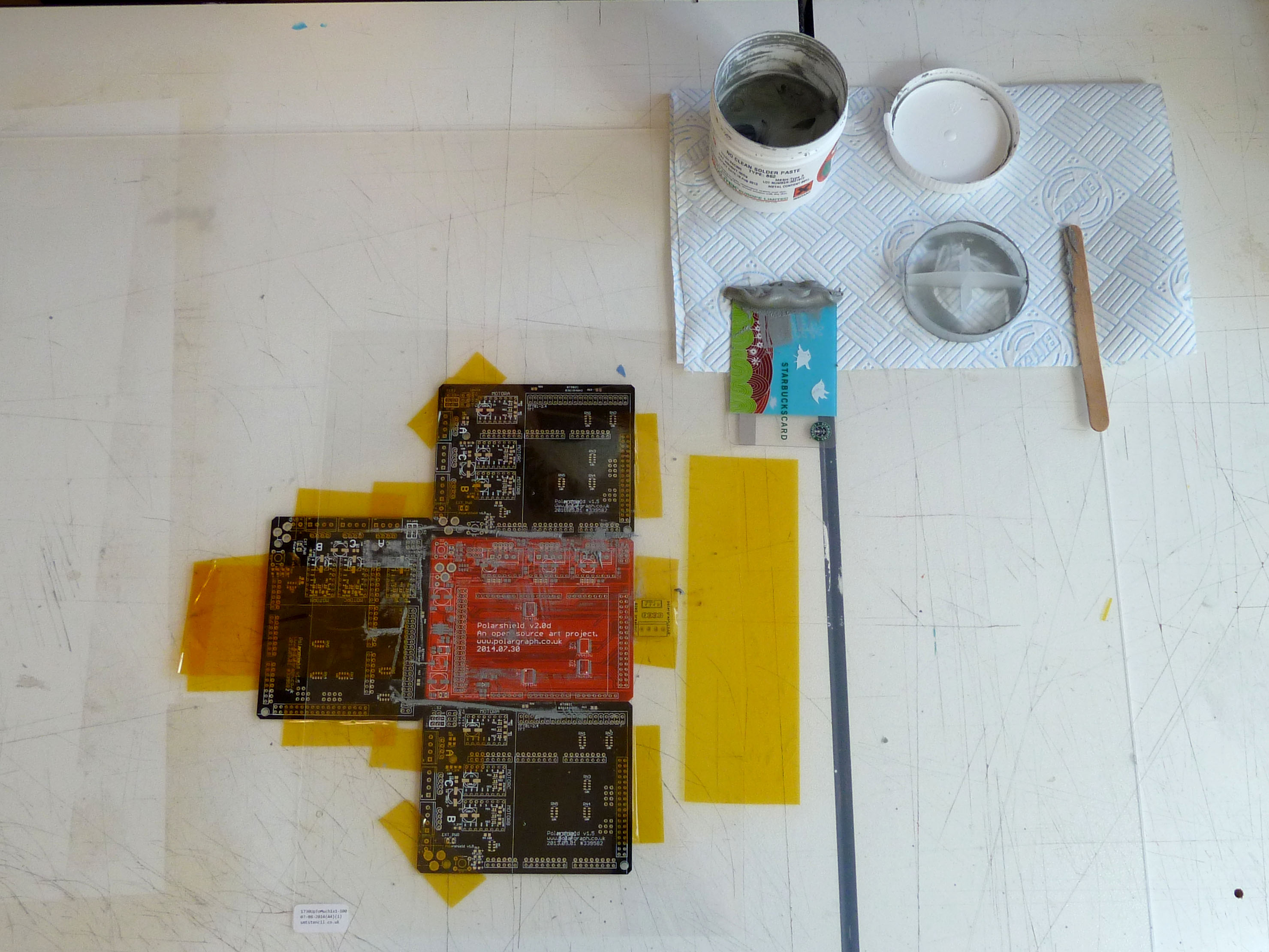
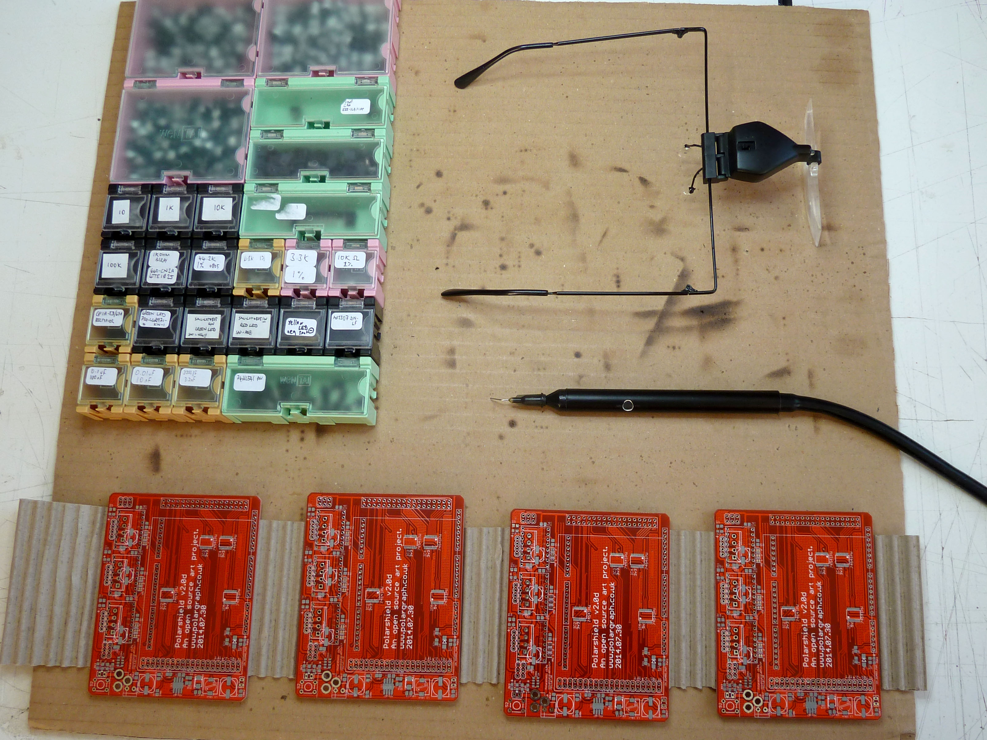
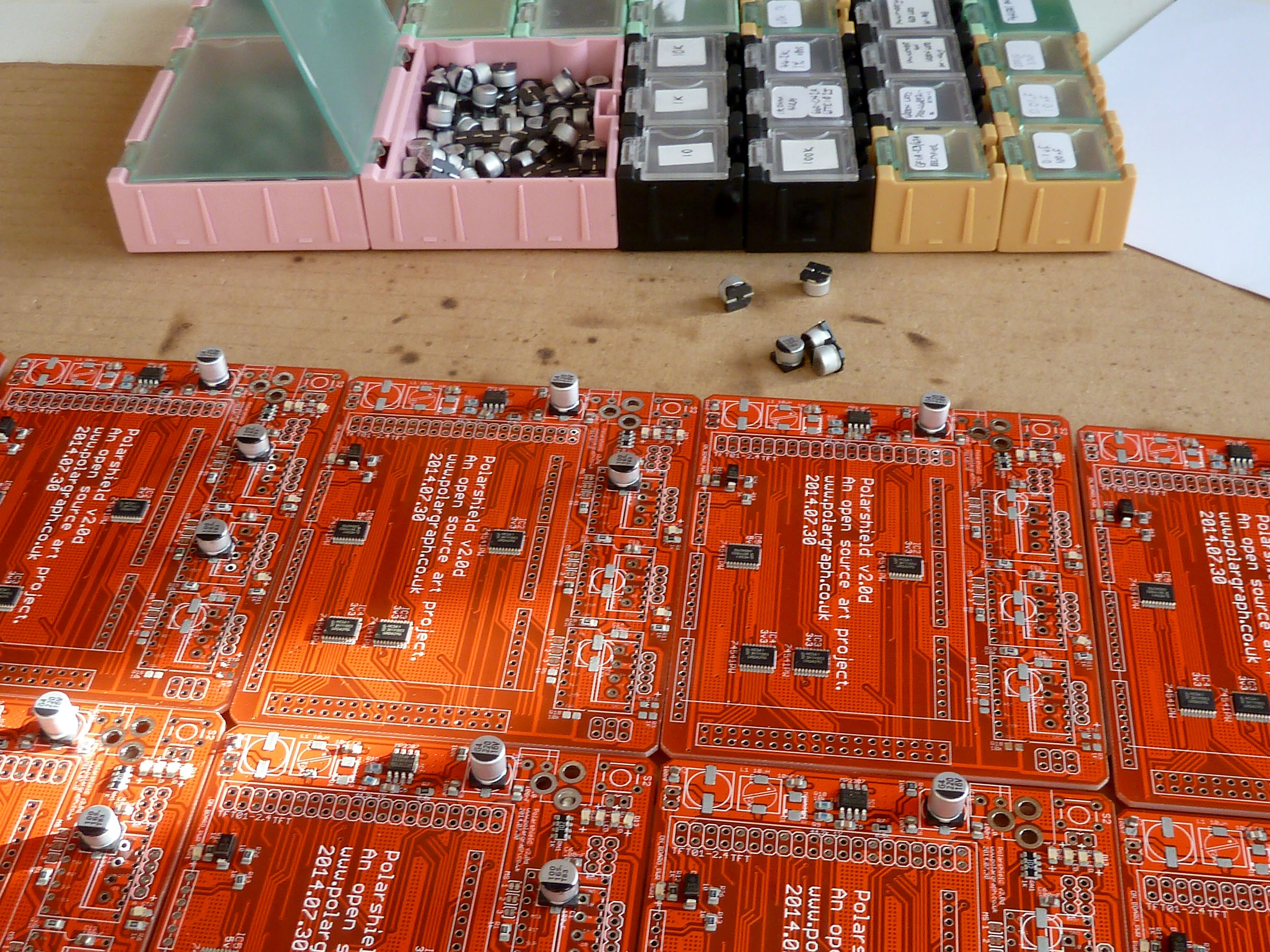
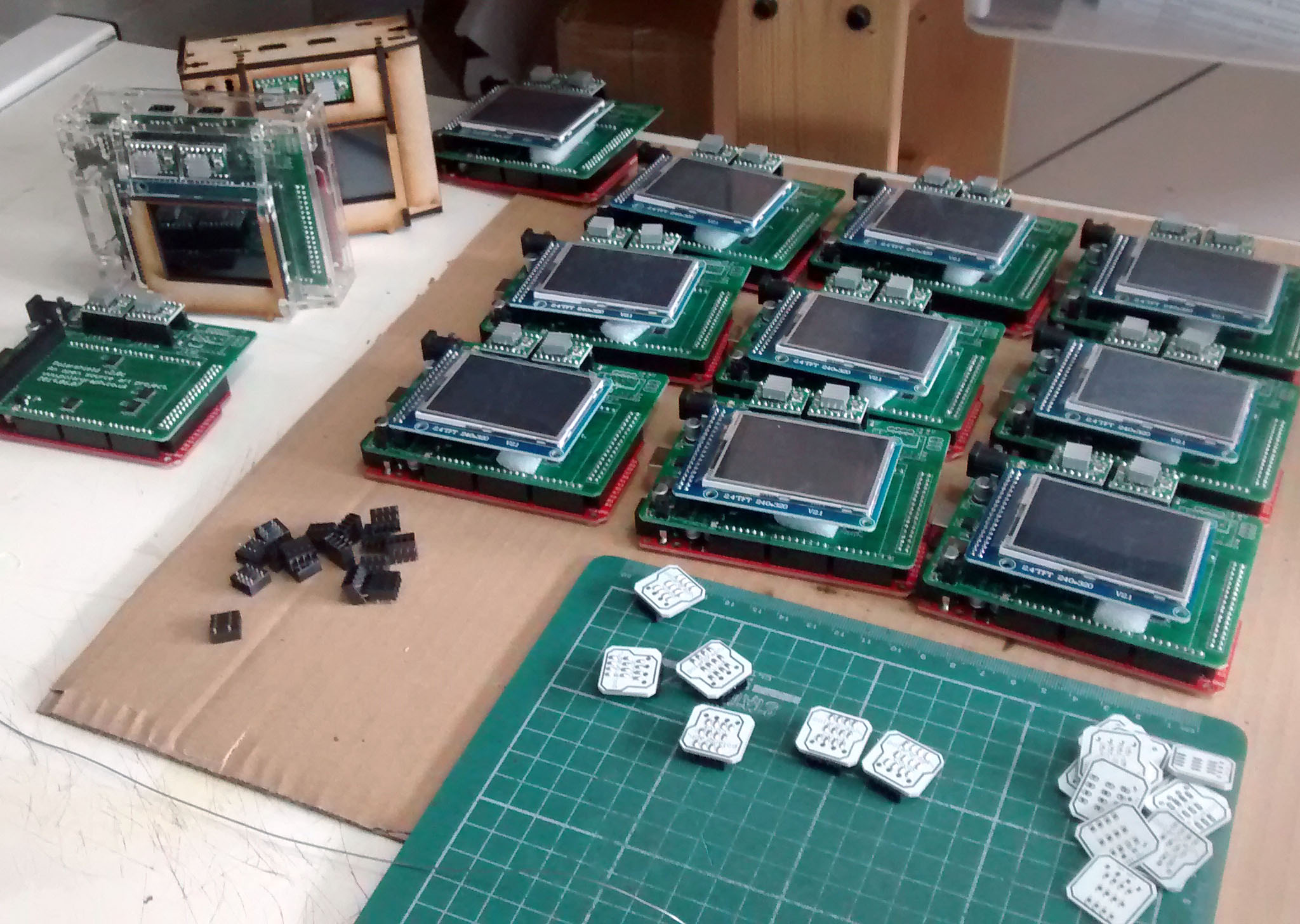
The Polarshield v2 has never been a reliable build. The straw that broke the camel’s back was earlier this year when I was building a batch and I ordered 20 boards, built them and only got six working Polargraph machines out of them. The LCD that it uses is growing to be somewhat esoteric in that configuration, and so it’s hard to debug. It uses a kind of simulated SPI which just isn’t reliable enough, or has too many odd interactions with other parts of the circuit.

The new 5v step-down power supply is an economic choice. I’m using a little off-the-shelf mini-assembly with a MP2307 and an inductor on it, rather than building the supply right onto the board itself. Amazingly, the little assembly is available to buy (ready-made) for less money than it costs me to buy a single MP2307 chip on it’s own.

The ESP-32 is a little cheaper than a good Arduino Mega-2560 clone. The current Arduino toolchain is a bit of a dog to set up, but dedicated developers has done an amazing job porting libraries to it. It’s dead fast and has a good small footprint. Mega-2560s are huge. Natively running at 3.3v is a bonus and performance with SPI-based touchscreens is phenomenal.

What’s next

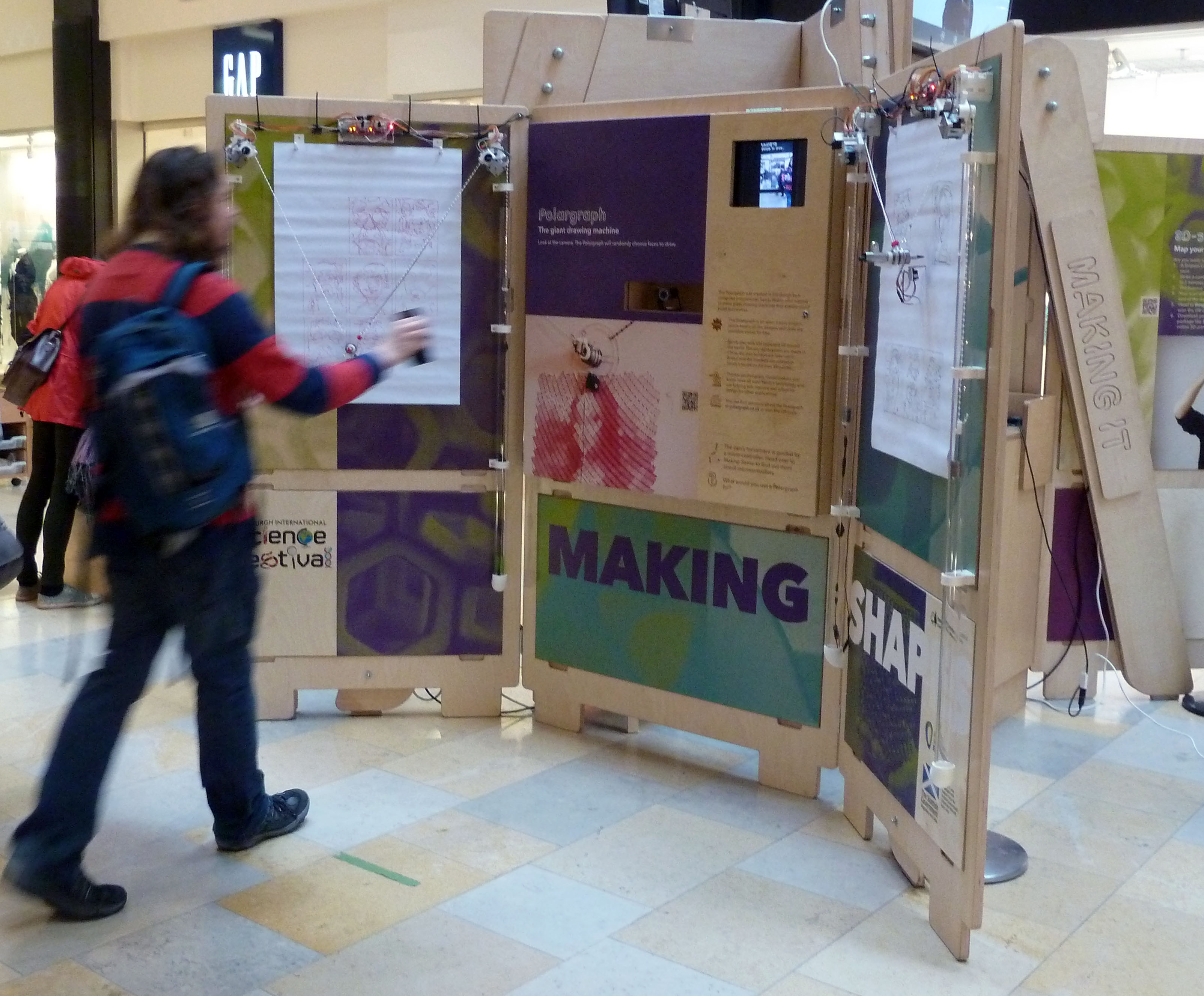
This is a platform that could easily take us into PolargraphPro territory, with encoders and endstops to make for a safe and reliable continuous drawing experience. The MCU is powerful and the wireless features are very tempting.

However, I have no immediate plans to implement any new features and will focus on getting old ones ported and re-worked where necessary. I’ll probably take this opportunity to dump a few lesser-used features too.

Mailing list

If you want to be alerted when these reach stock, or you’re interested in email updates about the project, you can sign up to my mailing list and choose what kind of things you want to hear about:

Polarshield v2.4 compared

I got a pile of boards back from the maker recently: Polarshield v2.4 (https://github.com/euphy/polarshield_hardware). Here it is alongside the 2.2 version (on the left)  to show the progress.

Polarshield v2.4 (compared to 2.2)

Not much right? There’s no revolution, indeed, but a couple of minor changes that makes it easier to build.

  1. More surface mount parts. The tactile switch in the top-left is now surface mount. SMT parts are just quicker to work with.
  2. Moved the microstepping jumper solder pads to the back of the board, and freed up a load of space.
  3. Squished four of the 1k resistors into another 4-row resistor network. This is the smallest part I’ve ever used, 2x1mm, you can barely see them on the picture. There’s one between the two motor driver sockets, and there’s another below the stack of LEDs on the top-left. This makes pick-and-place much faster. I’m not convinced the super-high density was a good idea though – it is far less tolerant of sloppy placing / solder paste application. We’ll see.
  4. Better designed for soldering with hot air, and iron. Some of the traces on the board were sometimes difficult to heat effectively, without also over-heating the component. The electrolytic capacitors were particularly problematic. I’ve routed the traces less efficiently in some cases, so that they have more copper that I can heat with the hot air pencil.
  5. LEDs are all orientated in the same direction. The old board has them pointing everywhere, so I was always spinning the board around. v2.4 has the anode to the right-hand side in every case. It’s to reduce the chance for placing errors.
  6. The holes for the DC power jack are placed off-centre, so the solder tabs are a friction fit. It makes the part self-aligning. Nice work sparkfun!

And the great thing is, it works, ha!

I’ve been taking some time off the Polargraph shop lately, because of work pressures and a couple of other things. It’s been really nice not to have to rush to the workshop every hour of the day to keep on top of things, and I’ve been able to do a little development here and there.

I think I’ll be back eventually, but maybe in a couple of weeks, and I might try a different manufacturing pattern.

Labelling evolution

My manufacturing process is always sometimes evolving. It’s not a complicated one, but there’s enough steps and nuance that I benefit from reminding myself what I’m supposed to be doing.

A run of bad Polarshields last year prompted me to start being a lot more careful about how I assembled and recorded the assembly of them. I started putting little journals on each one, which were just a strip of sticky tape with any story on them. Anybody who bought a Polarshield will have found such a thing.

Quality control labelling on Polargraph gear

I recently kicked myself a couple of times in a row when I thought I’d forgotten to test a certain aspect of the board, and had to open up a pile of sealed parcels to find out. Fortunately in that case, there was no problem, but I made up some new labels to help me not make a mess in the future.

The evolution is in the pic. The QR takes you to Building a Polargraph from a vitamin kit on the wiki. The final version is less handsome, but more useful, and there’s a beauty in that trade-off.

I like seeing these kinds of “work in progress” pics on other makers’ blogs.

Polargraph at the Edinburgh Science Festival 2015

Once again, the Polargraph Pro is featured as part of the Edinburgh Science Festival’s Making It touring exhibit, stationed until the 19th of April 2015 in Ocean Terminal Shopping Centre down the road in Leith.

P1050631_c_p

Tricking the machine with smartphones

I was a bit nervous about having the machine presented in such a uncontrolled environment (it was in the National Museum last year), but it’s been remarkably low-maintenance during it’s first week.

Some better than others

Some better than others

For this year’s outing, there were a very small number of changes to the firmware, mainly to add a feature to support a button and an indicator LED on the circuitboard that is controllable via commands, and used to signal to the Science Communicators that it needs it’s paper changed.

The changes to the Polarweb controller software are a little deeper, and there’s now a visualisation video stream published to a browser so you can see what the machine sees, and what processing it’s doing. Worked pretty well, but taxed the original laptop a bit much (it was an Atom), so the machine has been upgraded.

Other upgrades:

  • Minimum face size, so only people close-up get recognised and drawn
  • Path sorting to make for more efficient drawing (I hope to pull this work into the general Polargraph Controller some time soon)
  • Except for changing the paper, there is no manual intervention required during operation
  • Tracing controls are available in the interface to change posterisation levels, minimum path length, maximum path count and smoothing
  • The pen lift servo wire is routed more neatly, and uses spring-loaded retractable cable spools rather than the coiled cable that got stuck all the time
  • Drawing sequence can now fixed bottom-to-top so that pictures can be cut out and taken home as soon as they are drawn

How to make a PolargraphSD

Just thought it might be interesting to see the steps that go into making a PolargraphSD. I’m curious about this kind of stuff, and I love work-in-progress pictures. So I assume you do too.

P1050515_c_p

Apply solder paste.

Starting with the PCB mounted in a jig made of other PCBs, I use a plastic stencil, and a card to squeegee on the solder paste. This can be messy, but it’s very fast, takes less than a minute for each one.  I have taken to making up batches of 10 polarshields at a time, it takes a reasonable weekend, or a long day from beginning to end.

P1050576_c_p

Sometimes bits get missing, or I accidentally rub off the paste during placing, and I use a little syringe to do touch-up stuff. Afterwards, there’s these nice little pillows of paste on all the pads.

P1050580


Pick and place

I’ve got all the parts I need in little boxes, and empty out about the right amount of parts, sort through the pile and turn them over and line them up with a pair of tweezers. I used to use tweezers to place them too, but have recently got a cheap vacuum pickup tool that makes it a bit quicker.

P1050582_c_p


Using magnifiers and good lighting, dealing with these tiny parts is much easier than I thought it would be.

P1050583_c_p

I place most of the ICs with tweezers, because I get a bit more control over their orientation – they have a tendency to swing around a bit on the tip of the vacuum. The really big parts (electrolytic caps and the inductor) are just placed with fingers.

Soldering / reflow

I’ve got a hot air gun (Atten 858D+) that I used to take 8 minutes to melt all the solder paste on each board, and I still use that for touch-up and fixing. The last couple of batches of Polarshields have been soldered with a little home-made reflow oven though. This is a mini oven, retrofitted with a Zallus temperature controller. The temperature controller was a Kickstarter I backed at the end of last year, and it seems to work really well. Though the whole contraption looks like junk – but that’s my fault.

P1050585_c_p

The boards go in two at a time, and cook for 6 minutes, releasing all kinds of (probably deadly) fumes. I only use lead-free solder in all my stuff, so it’s not the nice smell you get out of rosin-fluxed lead solder. I miss that. My old tutor told me that eating plenty of jam would help ward off the poisoning that we would all get off the solder fumes. I like the story.

Now comes the really boring bit.

Through-hole soldering

There doesn’t seem to be any way to short-cut this one, just got to cut lots of parts to length and solder them all in. Using the kind of small iron tip that is useful for touching up SMT work makes this an absolute misery, so use a big clumsy chisel tip instead to whizz through.

P1050593_c_p

There are 156 points of through-holes to solder. During soldering, I sometimes spot things like this:

P1050596_c_p

There’s a solder bridge between the first three pins of the IC. This is irritating, but out of 10 shields, there’s normally four or five bridges like this that need a touch-up. Fix it with some solder braid. In this case, I noticed the IC was a bit skew-whiff on it’s pads too. I am not sure if it is something about the heating profile, but it seems like the parts don’t always get “pulled” onto their pads by the solder tension during flowing. At least, not as straight as I saw when I was using the heat gun. So with this IC, I reflowed it using the heat gun, and just nudged it to straighten it up. Afterwards, I wash the board with Techspray Flux remover to clean it up. Add stepper drivers and LCD, and it’s ready to test.

Testing

Upload the latest version of polargraph_server_polarshield and see what happens. Well, I just got a white screen. So I took another look at the board and spotted another solder bridge. Fixed it.

Testing involves plugging in a couple of steppers, a servo and an SD card and running a test script from the card. If the motors move smoothly and quietly, and the servo wiggles, and the LCD responds to touch, then it’s cooked.

IMG_0043_c_pFor full PolargraphSD kits (with the motors and cables), I do another test of the same routine before I pack everything up, to make sure the particular motors and the cables are correctly constructed, and they all work together.

Case

The case is made up of 16 laser cut parts, and is fastened together with six M3 nuts and bolts, tab and slot style. I try to leave as much of the protective film on as possible during assembly.P1050604_c_pI enjoy peeling that stuff off when I buy a new product, so I assume other people like it too. It stops my grubby fingerprints spoiling it too. I’ve got white gloves and everything, for this bit.

So now you know. Tune in next week and I’ll show you something equally as thrilling, how I clean my oven or do the hoovering or something.


Huge Portland Design Week project

It’s great to hear from polargraph people from around the world, and I was especially pleased when it turns out they’ve had zero problems, and have added their own features to the standard kit.

IMG_1725You can see this is a big machine (12ft wide, 8ft tall), drawing some promo stuff for for an agency in Portland. Notice the extra pulleys that have been added to reduce the drop of the counterweights – liking that.

This isn’t merely a really big machine though: The makers, Olivier and Evan spend 55 hours drawing the motorbike above and decided they could do better, and came up with a very sweet little script that will read your optimise the saved command queue and … make it efficient!

motorcycle_originalAbove is what the original pen path looks like. No surprise it took 55 hours really. The path planning has never been efficient, and just draws the file as it reads it, from top to bottom.

Running an exported command queue (previewed above) through this Polargraph Optimizer results in:

motorcycle_optimized

Which I think we can agree is much more sane. Evan reckons this is 3 1/2 times faster, and I don’t doubt it. Brilliant!

Thank you to Olivier, Evan and Squishymedia for supporting the project, and for giving back too. I’m going to try and pull those algorithms into the Polargraph controller at some point, but until then, I’d recommend that anyone doing really complex drawings should have a look at this.

Most of the things I end up talking with folks about about are troubleshooting and helping get things working, and I feel endlessly guilty about putting you through all that. It’s really gratifying and refreshing to hear success stories – and when someone cares enough to contribute, it means a lot. Even if it is embarrassing because it shows up all the bits I never got around to finishing…

Source: Polargraph Optimizer on github


Finally introducing… PolargraphSD v2!

I wondered if I would ever get here to be honest. It was only the thought of dozens of angry Polargraphers chasing me into the town square with pitchforks that gave me fear hope.

PolargraphSD v2

I have stock! The first couple of machines will be being posted or collected during this week.

PolargraphSD v2

To the folks who have so far only paid a deposit: I’ll be sending you an email out when your machine is ready, and asking you to go and pay the balance. To those kind, generous trusting souls who already paid up front during the pre-order period: Thank you. Without that we wouldn’t have even got this far. I will drop you an email to confirm your delivery address (in case it has changed in the meantime), but unless I hear back in the next few days, your machine will be winging it’s way to you as soon as it’s built.

PolargraphSD v2


Seriously, thanks for being so patient. This machine is a much better product because of it, I have much more faith in it now than if I’d had to rush it out the door two months ago (eek, when I said I would). I really hope you’ll enjoy using it.

I’ll do a bit more of an “unboxing” guide in the future. There is a still a long waiting list for this machine, but now stock actually exists, it’ll be moving fast at least. It can be bought along at The Polargraph Shop.


Slow going

Slow going, but … going!

IMG_20140630_130446635

The hardware is working fine now, working with all kinds of SD cards, all servo motors and all power supplies, but I’m waiting for the full set of the new cases to be cut and sent.

The case is funny. Probably the ugliest thing I’ve ever made, but I quite like it.

IMG_20140630_130513459

Choice between clear acrylic and MDF – any thoughts? The clear looks shows fingerprints but looks pretty snazzy.


Parts are slowly rolling in

A big lovely batch of shiney stepper motors arrived today. My electronics parts came last week (£650 of ICs and connectors – that is always so disappointing to receive). I’ve got a pile of touchscreens, and stepper motor drivers, and a big bag of drive sprockets. A big box of MEGA2560 R3s. Red ones.

The first version of the Polarshield v2 was tested and found wanting, so I’m expecting the samples of the final version at the beginning of next week. The first batch of PCBs took a week to arrive, this batch has taken three weeks so far. I am looking for a new supplier.

So unfortunately, that has eaten up all of my contingency, and then some, and so I’m already behind before I’ve even started. Great!

sn

Polargraph Pro Preview

Hello, I’m getting excited about the new Polargraph installation that’s been eating up all my time recently. IMG_20140327_160058025_HDR This is part an exhibition called Making It, itself a feature of the Edinburgh International Science Festival, and it’ll be running in the Grand Hall of the National Museum of Scotland, here in Edinburgh, for most of next month (April 2014).

IMG_20140330_112312329_HDR

I’m just putting some finishing touches to the machine and the control software.

There’ll be more of an update when it’s up and running.