Touchscreen issues

I’ve had a rash of problems with the touchscreens on bare Polarshields!

Over the last six months or so, I’ve noticed an issue where the touchscreen doesn’t work after booting. It looks ok, and updates fine, just no response to tapping.

I solve this by discharging the static from the device, while it is unplugged. I do it by either leaving it for a couple of minutes, unplugged, or by touching the metal USB socket housing, and rubbing an earthed piece of metal (it’s a wall-mounted shelving rack that I know happens to be screwed into the grounded metal studding in the wall). Handle it carefully, by the edges of the board while you’re plugging it back in.

I didn’t write anything about this until now, because until recently I was hoping this was a problem that only I was having! I think the touch IC must be being blocked during it’s boot process, or something like that.

I have handled hundreds of these, and the screens actually breaking down somehow is very rare. Having them rebel against their touch programming happens every day though, and I always fix it this way.

You can test your screen by using the UTFT and UTouch example sketches, but with these updated lines:

UTFT        myGLCD(TFT01_24_8, 38, 39, 40, 41);   
UTouch      myTouch(11, 12, 18, 19, 2);

Good luck!

Polarshield now compiles in Arduino v1.6

what the hell are you doing?

Well, I’m glad you asked.

The drawing above is by Ben Young. I love it.

Released new code bundle. Only code change is that I’ve mended this line about how the crc_check pre-computed value table is defined in polargraph_server_polarshield.ino. The only purpose for this is to allow it to compile in the newest versions of the Arduino IDE (1.6x). If you aren’t using that version, you don’t need to update anything.

Also updated the UTFT library to v2.81, for the same reason (Arduino IDE 1.6 compatibility).

https://github.com/euphy/polargraphcontroller/releases/latest

G-Code importing, and a bit of calibration help. Controller v1.2

I am generally filled with forboding about adding features to the Polargraph Controller. I remember it as being a twisted and unstructured wild-west kind of program. However, whenever I actually get into coding in it again, I always regret my fear, because I get something really useful done, in a really short length of time. Last weekend was no different.

Download the result: Polargraph v1.2 code bundle, or read on… If you dare.

G-Code importing

Polargraph exemplar Kongorilla has made a number of not-so-subtle hints about the impediments he runs into in getting stuff prepared for drawing. There’s a workflow that is sometimes fairly tortuous, even if it is logically straightforward. The controller has only been able to import SVG files, so a run through inkscape has always been the last step for most people.

IMG_20150519_172018910

The load vector dialog now allows .gco and .g files too, so anything that emits g-code files is also now a contender. Now, it’s fairly simplistic, understands only G0 and G1 commands, and the Z-axis implementation is rudimentary, but it does mean that it can swallow the output of wonderful things like Dullbits’ beautiful Death-To-Sharpie sketch.

The Z axis automatically makes a choice about when the pen is up or down. The very first Z axis change is ignored, and the second one is used henceforth as the “down” (drawing) position. Any position other than that second position is considered a travel (non-drawing_ position. This is because dullbits has Z1.0 as it’s drawing position and Z0 for travel, whereas inkscape(‘s gcodetools) seems to have Z-0.125000 as it’s drawing position, and moved to Z5.0 for travel. So opposite directions.

Usually the first Z movement is to shift into travel mode, in order to safely get to the start point, and then the second Z movement is to drop the pen / tool. Scripts that have funky stuff going on in their Z movement might need a bit of manual editing to work.

It’s immediately become obvious that .gco is not a standard enough file extension, so I’ll change it to .gcode as well for the next release. For now, just rename the file.

Preview cord offset

A commonly reported problem is that a drawing is short and fat, or tall and thin, or has a curved top or bottom, or it’s sides diverge.

There is a page about this in the Polargraph wiki, but it’s quite hard to diagnose, and hard to explain in words. I added this extra feature to the queue preview that allows me to simulate common calibration errors.

The way I imagine this being used, is:

  1. Draw a shape. Oh no, it’s all wrong!
  2. View the command queue in the controller app. It looks right here!
  3. Adjust the preview cord offset until it the preview matches what happened on the paper.
  4. Look at the value of preview cord offset. If it is:
    1. Positive: Your home point is further from the sprockets than you’ve told the machine. This might mean your home point is actually further down than you’ve measured, or your machine is wider than you’ve measured.
    2. Negative: Your home point is closer to the sprockets than you’ve told it. The home point might be higher up the machine than you have measured, or your machine is actually narrower than you’ve measured.

Firmwares

Polargraph_server_a1 has been updated to v1.2, and while there is no new functionality for UNO owners, I have merged the old MEGA-only features in, and made them configurable at compile time. So you can use polargraph_server_a1 on a MEGA, and get the SD card reading, norwegian pixel, spiral pixel etc. I actually fully expect this to have broken a load of stuff, so please take care, and report bugs.

In other news, I’ve also been working on porting the Controller to Processing 2, but that’s not borne fruit quite yet.

Download the code: Polargraph v1.2 code bundle

How to make a PolargraphSD

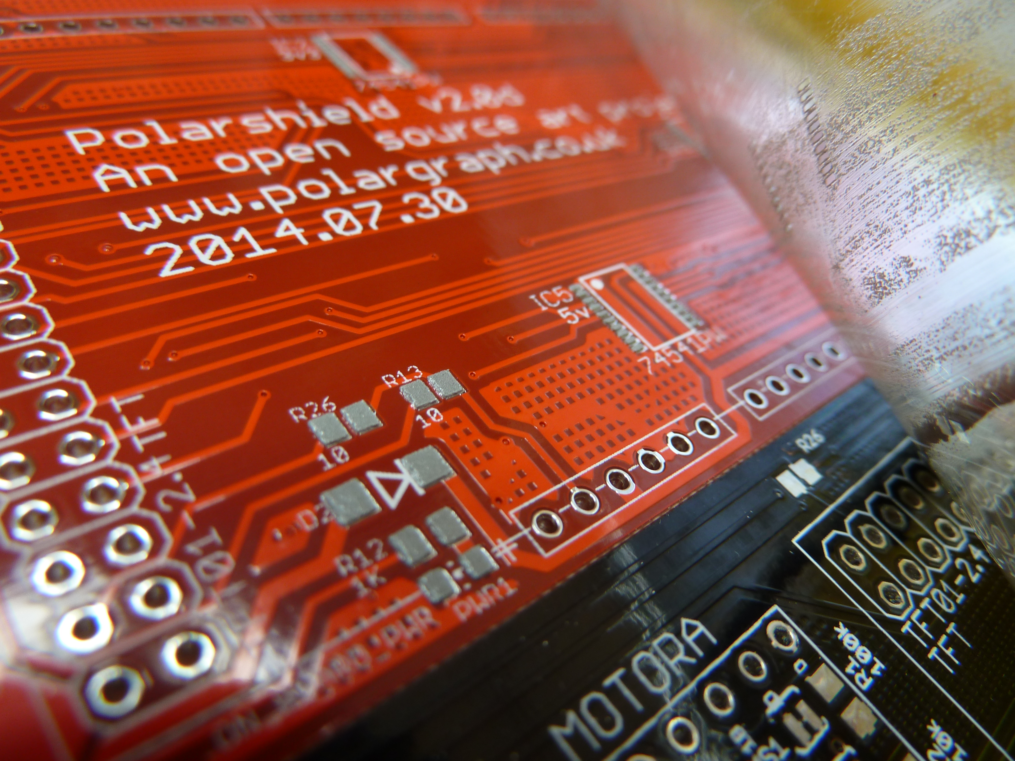
Just thought it might be interesting to see the steps that go into making a PolargraphSD. I’m curious about this kind of stuff, and I love work-in-progress pictures. So I assume you do too.
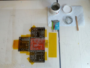
P1050515_c_p

Apply solder paste.

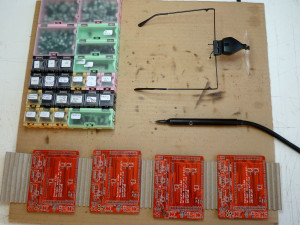
Starting with the PCB mounted in a jig made of other PCBs, I use a plastic stencil, and a card to squeegee on the solder paste. This can be messy, but it’s very fast, takes less than a minute for each one.  I have taken to making up batches of 10 polarshields at a time, it takes a reasonable weekend, or a long day from beginning to end.

P1050576_c_p

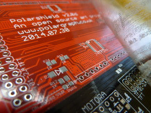
Sometimes bits get missing, or I accidentally rub off the paste during placing, and I use a little syringe to do touch-up stuff. Afterwards, there’s these nice little pillows of paste on all the pads.
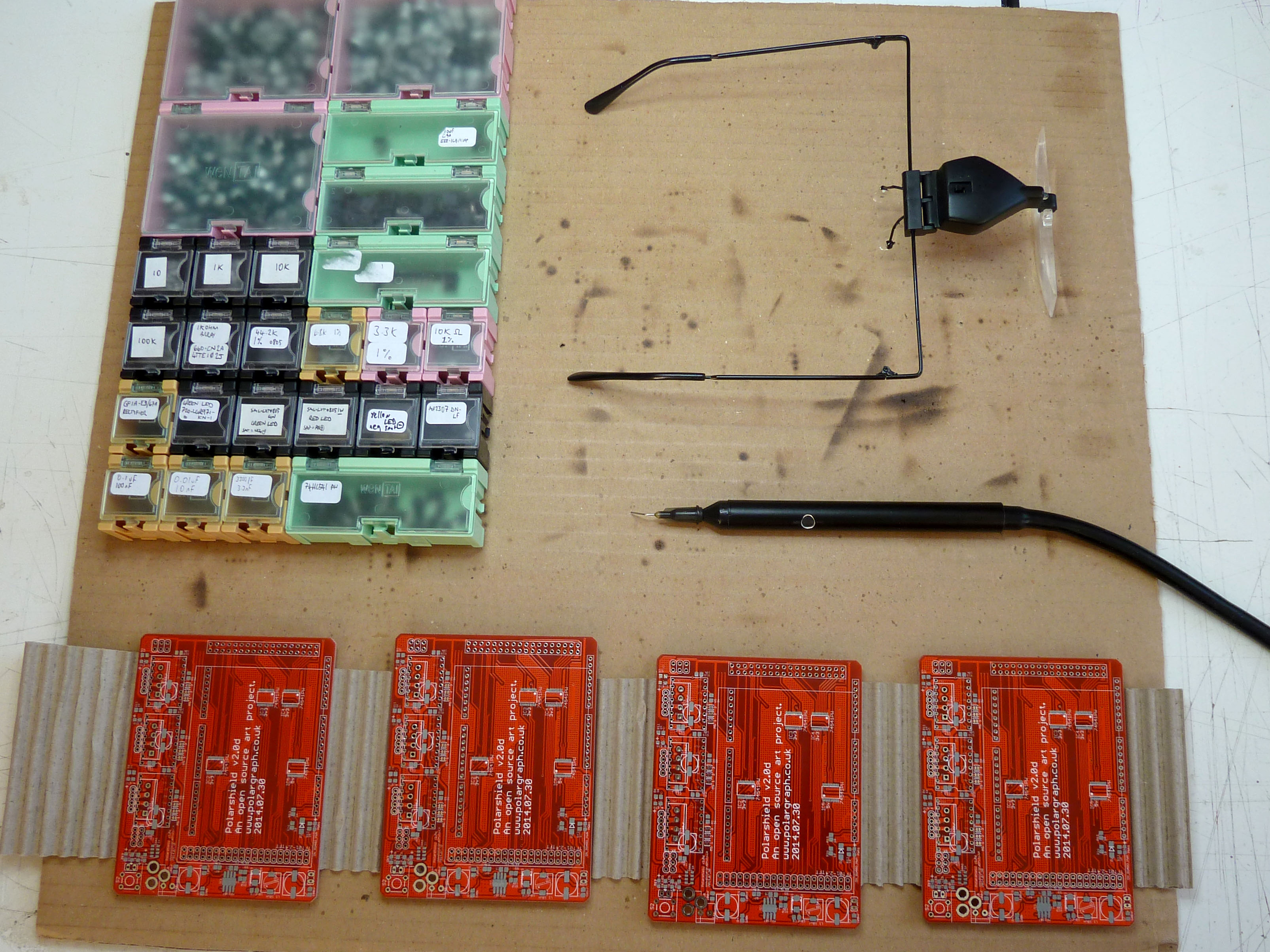
P1050580


Pick and place

I’ve got all the parts I need in little boxes, and empty out about the right amount of parts, sort through the pile and turn them over and line them up with a pair of tweezers. I used to use tweezers to place them too, but have recently got a cheap vacuum pickup tool that makes it a bit quicker.

P1050582_c_p


Using magnifiers and good lighting, dealing with these tiny parts is much easier than I thought it would be.

P1050583_c_p

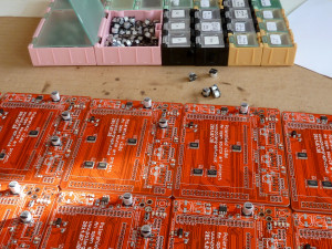
I place most of the ICs with tweezers, because I get a bit more control over their orientation – they have a tendency to swing around a bit on the tip of the vacuum. The really big parts (electrolytic caps and the inductor) are just placed with fingers.

Soldering / reflow

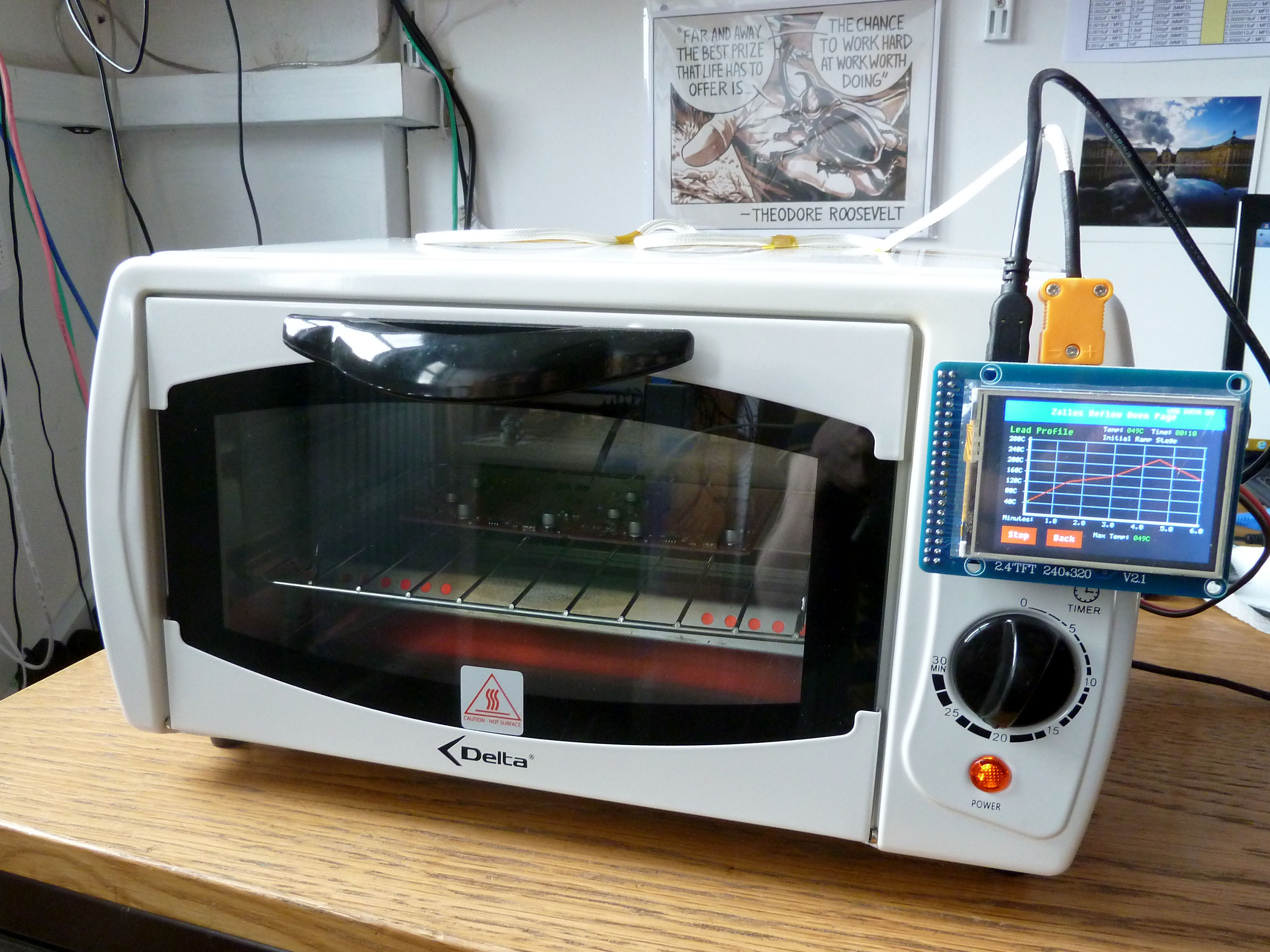
I’ve got a hot air gun (Atten 858D+) that I used to take 8 minutes to melt all the solder paste on each board, and I still use that for touch-up and fixing. The last couple of batches of Polarshields have been soldered with a little home-made reflow oven though. This is a mini oven, retrofitted with a Zallus temperature controller. The temperature controller was a Kickstarter I backed at the end of last year, and it seems to work really well. Though the whole contraption looks like junk – but that’s my fault.

P1050585_c_p

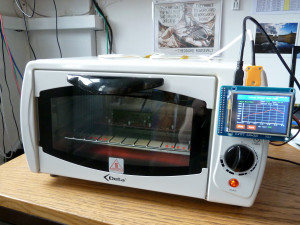
The boards go in two at a time, and cook for 6 minutes, releasing all kinds of (probably deadly) fumes. I only use lead-free solder in all my stuff, so it’s not the nice smell you get out of rosin-fluxed lead solder. I miss that. My old tutor told me that eating plenty of jam would help ward off the poisoning that we would all get off the solder fumes. I like the story.

Now comes the really boring bit.

Through-hole soldering

There doesn’t seem to be any way to short-cut this one, just got to cut lots of parts to length and solder them all in. Using the kind of small iron tip that is useful for touching up SMT work makes this an absolute misery, so use a big clumsy chisel tip instead to whizz through.

P1050593_c_p

There are 156 points of through-holes to solder. During soldering, I sometimes spot things like this:

P1050596_c_p

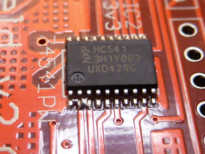
There’s a solder bridge between the first three pins of the IC. This is irritating, but out of 10 shields, there’s normally four or five bridges like this that need a touch-up. Fix it with some solder braid. In this case, I noticed the IC was a bit skew-whiff on it’s pads too. I am not sure if it is something about the heating profile, but it seems like the parts don’t always get “pulled” onto their pads by the solder tension during flowing. At least, not as straight as I saw when I was using the heat gun. So with this IC, I reflowed it using the heat gun, and just nudged it to straighten it up. Afterwards, I wash the board with Techspray Flux remover to clean it up. Add stepper drivers and LCD, and it’s ready to test.

Testing

Upload the latest version of polargraph_server_polarshield and see what happens. Well, I just got a white screen. So I took another look at the board and spotted another solder bridge. Fixed it.

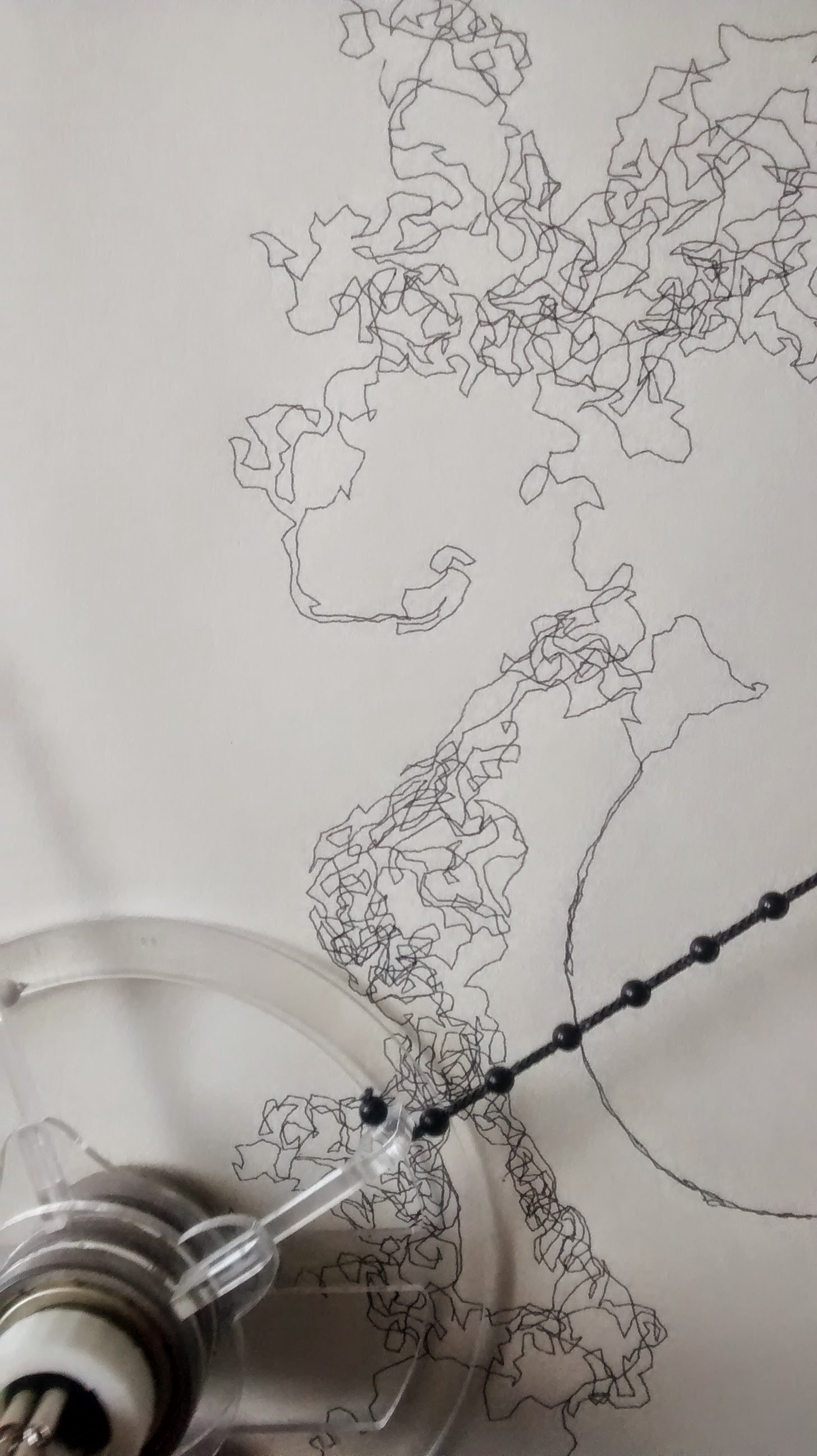
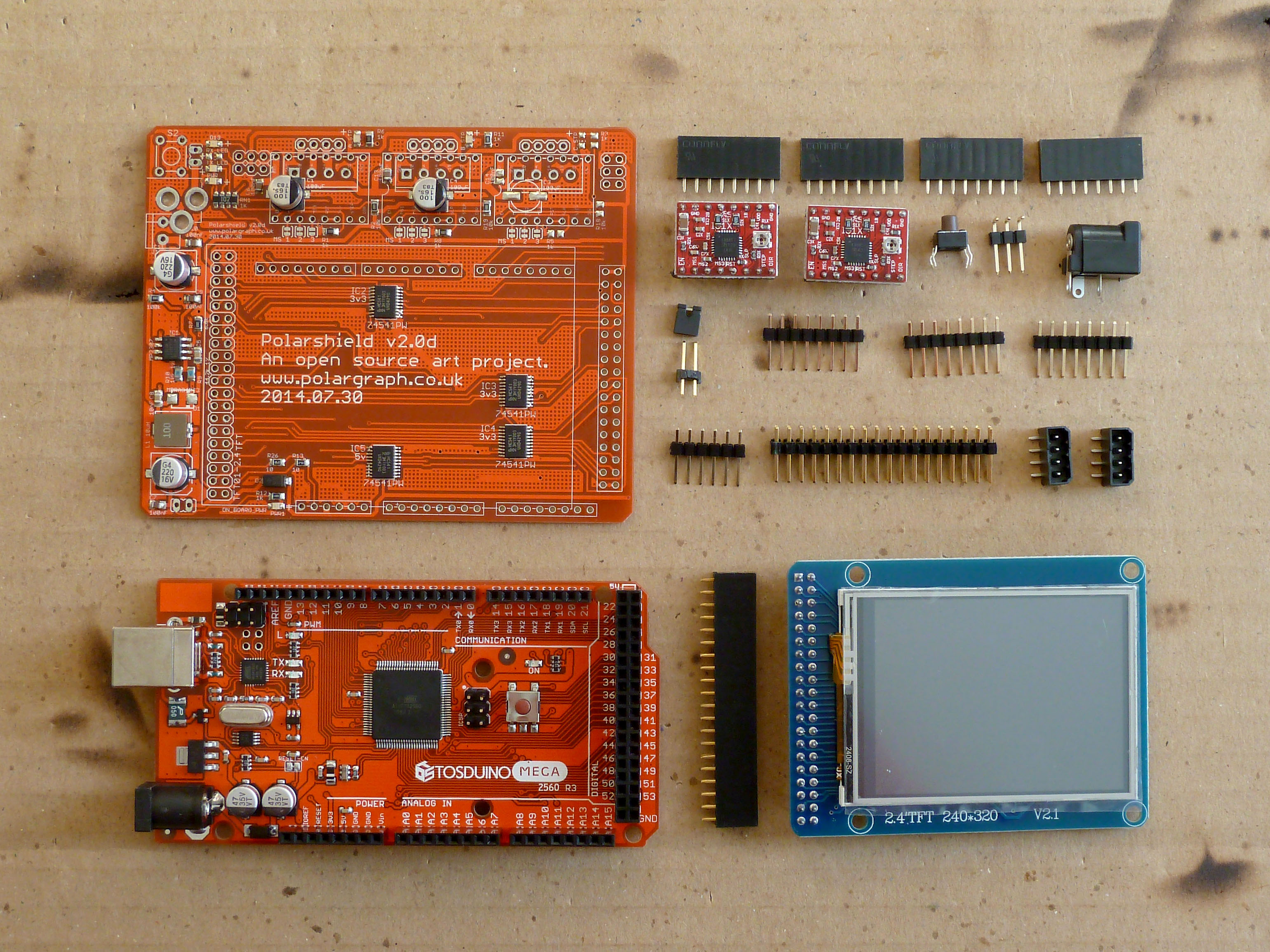
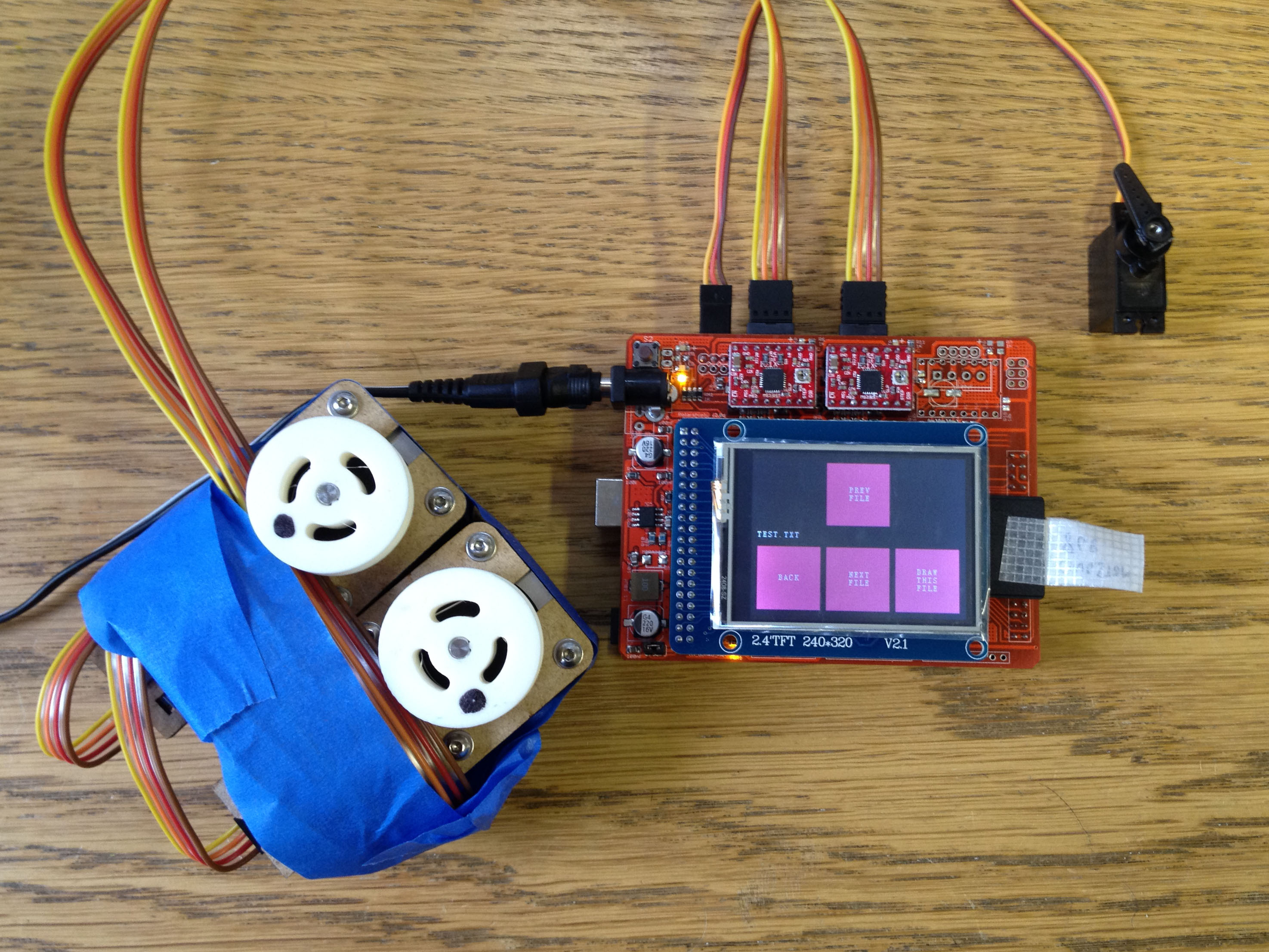
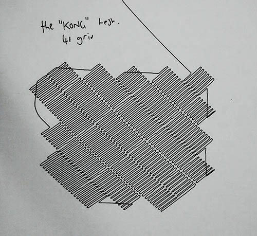
Testing involves plugging in a couple of steppers, a servo and an SD card and running a test script from the card. If the motors move smoothly and quietly, and the servo wiggles, and the LCD responds to touch, then it’s cooked.

IMG_0043_c_pFor full PolargraphSD kits (with the motors and cables), I do another test of the same routine before I pack everything up, to make sure the particular motors and the cables are correctly constructed, and they all work together.
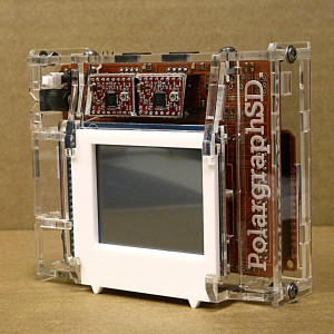
Case

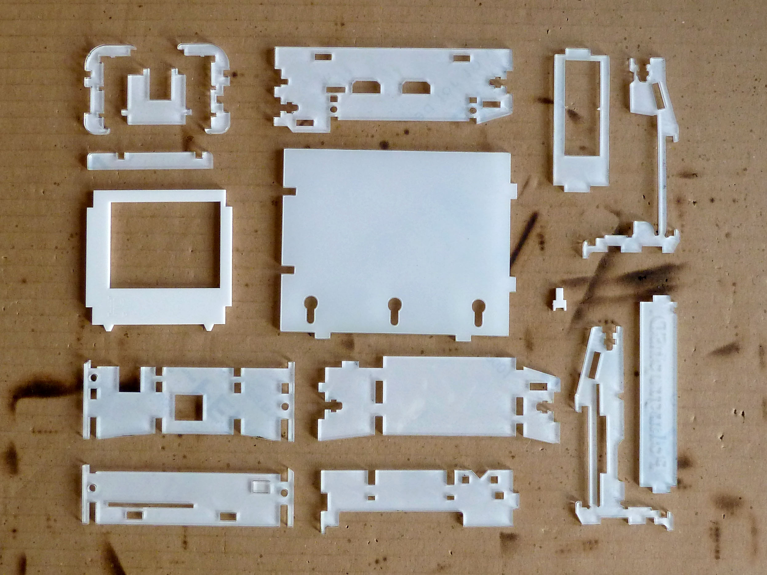
The case is made up of 16 laser cut parts, and is fastened together with six M3 nuts and bolts, tab and slot style. I try to leave as much of the protective film on as possible during assembly.P1050604_c_pI enjoy peeling that stuff off when I buy a new product, so I assume other people like it too. It stops my grubby fingerprints spoiling it too. I’ve got white gloves and everything, for this bit.

So now you know. Tune in next week and I’ll show you something equally as thrilling, how I clean my oven or do the hoovering or something.


Huge Portland Design Week project

It’s great to hear from polargraph people from around the world, and I was especially pleased when it turns out they’ve had zero problems, and have added their own features to the standard kit.

IMG_1725You can see this is a big machine (12ft wide, 8ft tall), drawing some promo stuff for for an agency in Portland. Notice the extra pulleys that have been added to reduce the drop of the counterweights – liking that.

This isn’t merely a really big machine though: The makers, Olivier and Evan spend 55 hours drawing the motorbike above and decided they could do better, and came up with a very sweet little script that will read your optimise the saved command queue and … make it efficient!

motorcycle_originalAbove is what the original pen path looks like. No surprise it took 55 hours really. The path planning has never been efficient, and just draws the file as it reads it, from top to bottom.

Running an exported command queue (previewed above) through this Polargraph Optimizer results in:

motorcycle_optimized

Which I think we can agree is much more sane. Evan reckons this is 3 1/2 times faster, and I don’t doubt it. Brilliant!

Thank you to Olivier, Evan and Squishymedia for supporting the project, and for giving back too. I’m going to try and pull those algorithms into the Polargraph controller at some point, but until then, I’d recommend that anyone doing really complex drawings should have a look at this.

Most of the things I end up talking with folks about about are troubleshooting and helping get things working, and I feel endlessly guilty about putting you through all that. It’s really gratifying and refreshing to hear success stories – and when someone cares enough to contribute, it means a lot. Even if it is embarrassing because it shows up all the bits I never got around to finishing…

Source: Polargraph Optimizer on github


Feedback in the controller

The Polargraph machine has always given useful responses, if you know where to look for them.

This last update (v1.10 polarshield, v1.9 _a1, v1.9 of the controller) introduces a machine message log that sits alongside the command queue:

feedback-line-not-on-pageErrors show up in pink. Above is an example of what could otherwise be a pretty opaque piece of non-cooperation if you didn’t know to check the debug console.

The main reason for this is to debug pixel drawing though. The relationship between pixel size, pen size and density is ultimately simple, but it is easy to find yourself in a situation where you expect a wiggle and get a straight line.

So now, when you change pen size, the machine itself replies suggesting the smallest grid you can usefully work with with this pen:
feedback-set-penwidthAnd if you try a smaller grid than recommended (or the exact size – because of rounding that happens during display, this is a bit hit-and-miss), then it draws a simple empty line on your page, and normally you’d scratch your head and wonder where your wiggle went, but now the helpful message is exposed (highlighted at the top of the message log below):

feedback-bad-sized-grid

Trying one grid increment larger (9), and the complaint goes away because the pixel is now big enough to hold a wiggle:
feedback-good-sized-gridThere are three kinds of message, DEBUG, INFO and ERROR. Debug (black) should normally be hidden unless you have a verbose/debug switch turned on in your firmware. Or I’ve forgotten to turn it back off before doing the release.

Info (white) are the standard ‘might be useful’ messages. Error (pink) means specifically that something you wanted to happen didn’t happen.

I have not yet added the message prefixes to all the functions in the firmwares, but I will get around to them as required.

The examples above (vector location and pixel debugging) are now in polargraph_server_polarshield and also polargraph_server_a1 in a limited way. Polargraph_server_a1 is too pushed pushed for space to be able to sacrifice much for this, so it will never be as helpful as wasteful old polarshield can be.

Give it a shot by getting the newest code bundle.

3rd August 2014: Little update!

To clarify: This firmware IS suitable for ALL PolargraphSDs and Polarshields, new and old. The source code is configured to run on the most recent version, with the most recent version of the LCD screen.

If you’ve got an older model and you want to compile from source, pay attention to the screen type configuration settings in the main polargraph_server_polarshield.ino file. There are three possible options, the comments there should explain what’s what.


New pixel preview styles

Polargraph Controller v1.8 adds a more representative pixel density preview style to the controller app:

native-pixel-size-preview

Edit your properties.txt file and set controller.density.preview.style=5

native-pixel-density-preview


or set controller.density.preview.style=2

These new modes are designed to give a better idea of whether pixels are going to fall off the page. That’s really annoying when it happens.

I’ve also taken out a couple of buttons that didn’t really do anything sensible any more.

It’s available here on the github page.

Also included in that bundle is v1.9 of the polargraph_server_polarshield firmware. This is really only intended for the new v2 polarshield, but should do no harm if you want to play with it. Well, I hope it doesn’t do any harm anyway.

The only new feature is that the pen-lift height (at up or down points) can be adjusted through the touch UI now, rather than just through the controller app.


Polargraph Server for Adafruit Motorshield v2

There’s been a bit of ongoing investigation about getting the polargraph firmware running with the new Adafruit Motorshield (v2). I have just got one of these shields recently, so have only just had a chance to work on it tonight.

https://github.com/euphy/polargraph_server_a1

The new Adafruit library is slightly bigger than the old one, and the polargraph_server_a1 firmware was super tight on space already, so I’ve split up the code into a set of features that can be easily enabled or disabled at compile time to save space:

  • PIXEL_DRAWING – This is pixel shading.
  • PENLIFT – Controlling a servo to lift the pen.
  • VECTOR_LINES – Drawing straight lines, aka vector plotting.

So to get this to fit on, you need to disable either PIXEL_DRAWING or VECTOR_LINES – can’t have both anymore, not with Motorshield v2.

For convenience, I’ve pre-compiled two binaries, one for Motorshield v1 (using AFMotor), and the other for Motorshield v2 (using Adafruit_MotorShield). The firmware for Motorshield v2 has pixel drawing disabled.

This is a bit of a pain, but I don’t see an acceptable alternative.

I haven’t tried this for actual drawing yet, because I haven’t got a machine made up that uses this system, but at least the motors move! Please let me know if there is any success – or otherwise.

Happy scribbling!

See also http://www.polargraph.co.uk/forum/polargraphs-group2/troubleshooting-forum5/motors-not-working-when-i-compile-but-hex-works-thread324/

This knowledge transferred to: https://github.com/euphy/polargraph/wiki/Polargraph-Server-for-Adafruit-Motorshield-v2

Polargraph Pro Preview

Hello, I’m getting excited about the new Polargraph installation that’s been eating up all my time recently. IMG_20140327_160058025_HDR This is part an exhibition called Making It, itself a feature of the Edinburgh International Science Festival, and it’ll be running in the Grand Hall of the National Museum of Scotland, here in Edinburgh, for most of next month (April 2014).

IMG_20140330_112312329_HDR

I’m just putting some finishing touches to the machine and the control software.

There’ll be more of an update when it’s up and running.

Mystery of the Gappy Drawings- new controller version

I have uploaded v1.7.1 of the controller here on github. I know it’s in the wrong place, but I couldn’t figure out restructuring the projects quite yet.

So, polargraph innovator Kongorilla pointed out that he was getting gaps in his pixel shaded drawings, some 8 months ago. I was baffled, but agreed that , forsooth, they were gaps. Like him, I’d seem them, but never seemed to be able to replicate them. Like a ninja, they seemed to melt into the night, leaving me with a haunted feeling.

a40k5-IMG_20140309_19193207622

Well, thanks to his work, including the sample drawing patch above, and encouraged by code sleuthing from Nosetinker (and literally no contribution from me), a solution has been found!

While the value for grid size is displayed as integers, internally it is handled as a float. In the example above, the grid size was displayed as 41, but was actually 41.5, internally. When the positions of each pixel were calculated, and rounded to the nearest integer, 41.5 became 41. The next pixel along was put at 41.5+41.5: that is 83, and there’s no rounding there, but that means that there is 42 steps between them instead of 41.

So one pixel is 0.5 steps too high, and the next pixel is 0.5 steps too low. Simple! I had thought it would be something more tricky than that – thanks to Nosetinker and Kongorilla for shining a light on this – sorry it took me the better part of a year to get around to doing anything about it.

Note – I don’t have a machine right here to test it with, so it still might be something afoot. There are no updates to the firmware, but it is included in the zip.

(Note the first version of this, 1.7 wasn’t right, hence the extra .1)